

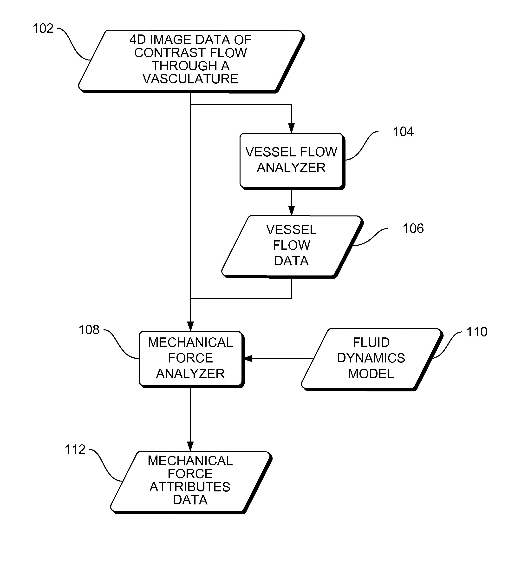
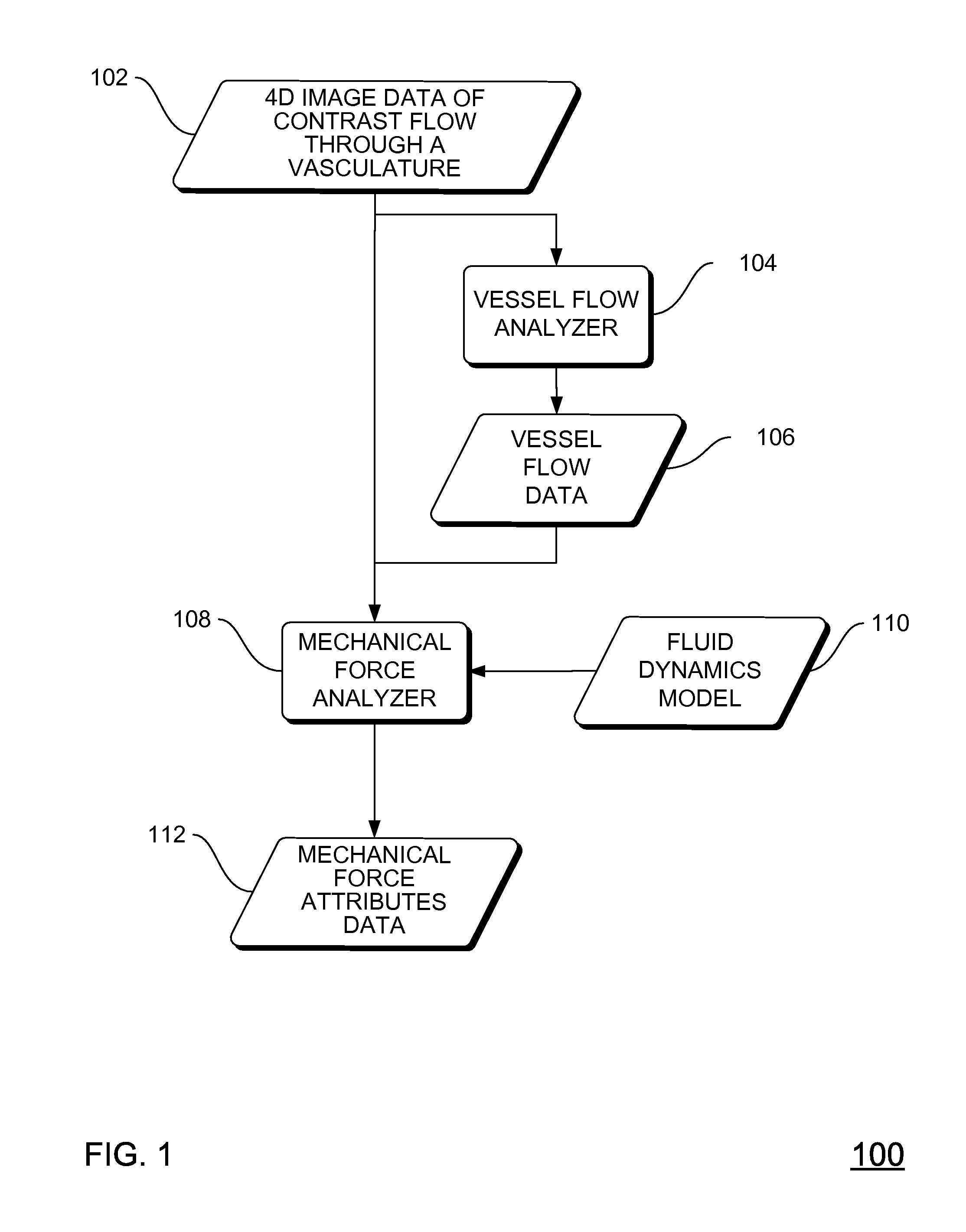
Determining mechanical force on aneurysms from a fluid dynamic model driven by vessel blood flow information
a fluid dynamic model and mechanical force technology, applied in the field of aneurysm imaging, can solve the problems of difficult detection of small aneurysms, tissue death or pressure in the head, and large hemorrhage,
- Summary
- Abstract
- Description
- Claims
- Application Information
AI Technical Summary
Problems solved by technology
Method used
Image

Examples
Embodiment Construction
[0026]In the following detailed description, reference is made to the accompanying drawings that form a part hereof, and in which is shown by way of illustration specific implementations which may be practiced. These implementations are described in sufficient detail to enable those skilled in the art to practice the implementations, and it is to be understood that other implementations may be utilized and that logical, mechanical, electrical and other changes may be made without departing from the scope of the implementations. The following detailed description is, therefore, not to be taken in a limiting sense.
[0027]The detailed description is divided into four sections. In the first section, a system level overview is described. In the second section, implementations of methods are described. In the third section, particular implementations are described. Finally, in the fourth section, a conclusion of the detailed description is provided.
System Level Overview
[0028]The systems in...
PUM
 Abstract
Description
Claims
Application Information