Variable compression surgical fastener apparatus

a technology of surgical fasteners and compression tubes, which is applied in the field of surgical fastener cartridges, can solve the problems of increased necrosis, needless reduction of blood flow to the tissue surrounding the cut-line, and decrease in the time necessary to achieve hemostasis, so as to maximize blood flow, facilitate healing, and limit the effect of flow

Active Publication Date: 2009-11-12
TYCO HEALTHCARE GRP LP
View PDF102 Cites 37 Cited by
  • Summary
  • Abstract
  • Description
  • Claims
  • Application Information

AI Technical Summary

Benefits of technology

[0011]The present disclosure is directed towards surgical stapling instruments configured to limit the flow of blood in tissue to effectuate hemostasis and wound closure, while maximizing blood flow in the surrounding tissue to facilitate healing. In particular, embodiments of the present disclosure include varying the formation of surgical fasteners in order to vary the compressive force that is applied to surrounding tissue. Further still, when the surgical fasteners are formed within tissue, recesses in the backspans of the surgical fasteners cooperate with the legs of the surgical fasteners to apply a compressive force to surrounding tissue, whereby a varying of the recesses corresponds to a varying of the compressive forces applied to surrounding tissue.

Problems solved by technology

It is commonly known that by increasing the amount of pressure applied to a wound, the flow of blood can be limited, thereby decreasing the time necessary to achieve hemostasis.
Each of the fasteners will generally apply a compressive force to the tissue sufficient to effectuate hemostasis, however, if too much pressure is applied, this can result in a needless reduction in blood flow to the tissue surrounding the cut-line.
Accordingly, too much pressure in the joining of tissue together may result in an elevated level of necrosis, a slower rate of healing, and / or a greater recovery period.

Method used


Image

  • Variable compression surgical fastener apparatus
  • Variable compression surgical fastener apparatus
  • Variable compression surgical fastener apparatus

Examples


Embodiment Construction

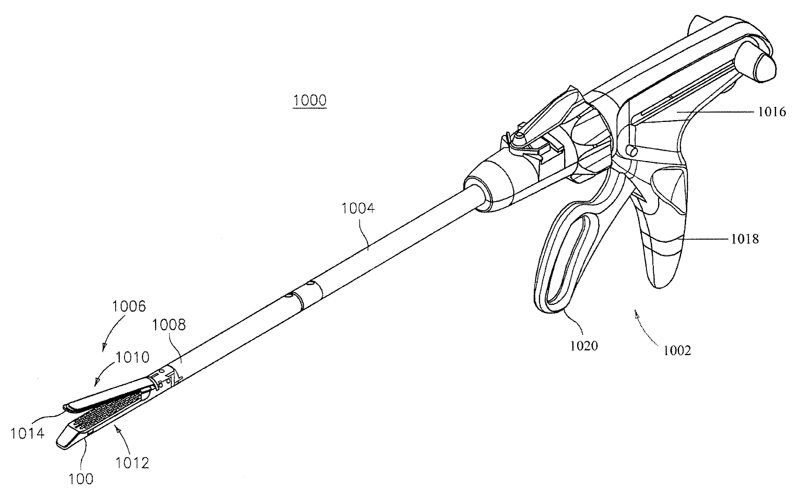
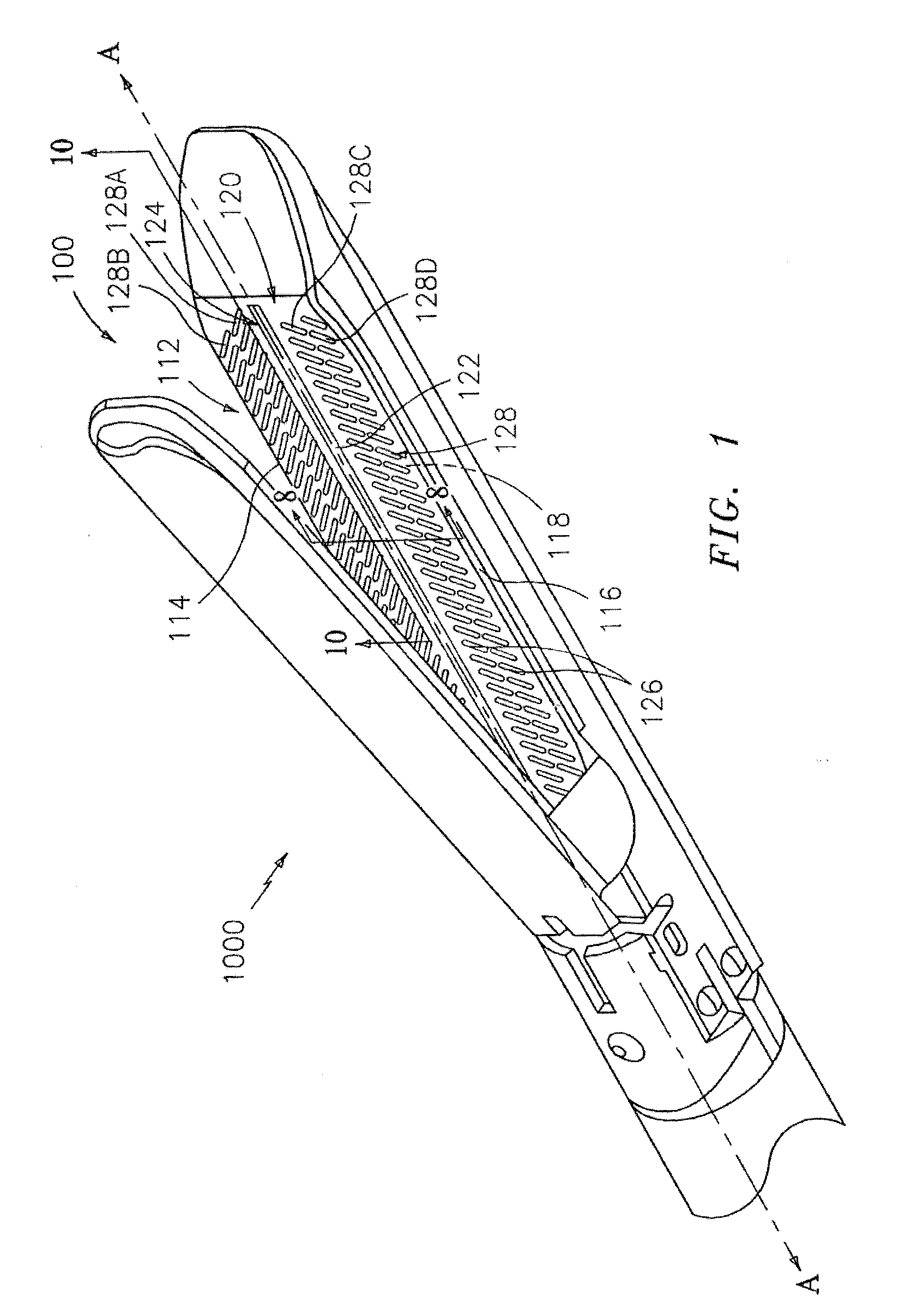
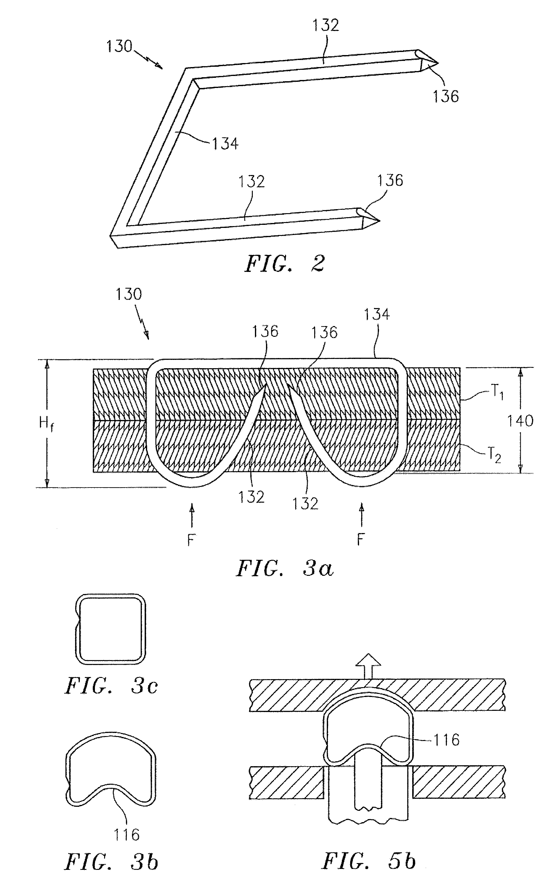
[0036]Various exemplary embodiments of the presently disclosed surgical fastener cartridge will now be described in detail with reference to the drawings wherein like references numerals identify similar or identical elements. In the drawings and in the description which follows, the term “proximal” will refer to the end of the surgical fastener cartridge that is closer to the operator during use, while the term “distal” will refer to the end of the fastener cartridge that is further from the operator, as is traditional and conventional in the art. In addition, the term “surgical fastener” should be understood to include any substantially rigid structure formed of a biocompatible material that is suitable for the intended purpose of joining tissue together, including but not being limited to surgical staples, clips, and the like. The surgical fastener can be made of any biocompatible metal, such as titanium or stainless steel, or any biocompatible polymer, including absorbable or re...


PUM

PropertyMeasurementUnit
compressive forceaaaaaaaaaa
pressureaaaaaaaaaa
sizeaaaaaaaaaa

Abstract

A surgical fastener applying apparatus includes an anvil section and a cartridge section, where the cartridge section and the anvil section are movable from an unclamped position to a clamped position to clamp tissue therebetween. The cartridge section has a plurality of retention slots. A plurality of first surgical fasteners and a plurality of second surgical fasteners are disposed within a corresponding retention slot. The plurality of first surgical fasteners has a first backspan with a first configuration and the plurality of second surgical fasteners has a second backspan with a second configuration. The first configuration is different from the second configuration. In addition, when the first configuration applies a first compressive force to tissue upon formation of the plurality of first surgical fasteners and the second configuration applies a second compressive force to tissue upon formation of the plurality of second surgical fasteners, the second compressive force is different from the first compressive force.

Description

CROSS-REFERENCE TO RELATED APPLICATIONS[0001]This application claims priority to, and the benefit of U.S. Provisional Patent Application Ser. No. 61 / 051,911, filed on May 9, 2008, the entire contents of which are hereby incorporated by reference.BACKGROUND[0002]1. Technical Field[0003]The present disclosure relates to surgical fastener applying apparatus. More particularly, the present disclosure relates to a surgical fastener cartridge that includes a plurality of surgical fasteners configured to apply varying compressive forces to tissue.[0004]2. Background of the Related Art[0005]Many varieties of surgical fastening apparatus are known in the art, some of which are specifically adapted for use in various surgical procedures including, but not limited to, end-to-end anastomosis, circular end-to-end anastomosis, open gastrointestinal anastomosis, endoscopic gastrointestinal anastomosis, and transverse anastomosis. Suitable examples of apparatus which may be used during the course o...

Claims


Application Information

Patent Timeline
Patent Type & Authority Applications(United States)
IPC IPC(8): A61B17/10
CPCA61B17/0644A61B17/07207A61B17/115A61B17/068A61B2017/07235A61B2017/07264B25C5/0292A61B2017/07228
Inventor VIOLA, FRANK
Owner TYCO HEALTHCARE GRP LP
Why Eureka
Try Eureka