Combustor with reduced carbon monoxide emissions

a technology of carbon monoxide and combustor, which is applied in the direction of machines/engines, mechanical equipment, lighting and heating apparatus, etc., can solve the problems of gas leakage of cooling gas from the plenum surrounding the combustor, and the formation of more co in the burner, so as to reduce the co emission

Inactive Publication Date: 2009-11-19
ANSALDO ENERGIA SWITZERLAND AG
View PDF10 Cites 6 Cited by
  • Summary
  • Abstract
  • Description
  • Claims
  • Application Information

AI Technical Summary

Benefits of technology

[0009]One of numerous aspects of the present invention includes a combustor with reduced CO emission.
[0011]Yet another aspect of the invention includes a combustor for a gas turbine engine having a split line and comprising burners arranged in an annular ring characterized by the separation distance between burners either side of the split line being at least two times the average separation distance between burners distant from the split line. The large separation distance reduces CO emissions caused by split line seal leakage. A further advantage is that, due to the significant disruption in the symmetry of the burner arrangement, thermo-acoustic stability is increased, enabling higher burner gas velocities and offsetting what would otherwise be a suboptimal use of available combustor circumferential space.
[0012]In a further aspect, the separation distance of the burners either side of the split line is at least four times, but not more than seven times, the average burner separation distance distant from the split line, thus eliminating the impact of split line leakage on the turbine engine CO generating while not extending the distance beyond a point of benefit.
[0014]In a further aspect, to maximize thermo-acoustic stability, a thermo-acoustic pulsation suppression or dampening device is located between burners either side of the split line, thus efficiently and advantageously utilizing the space made available by the burner arrangement. In a further aspect, the burners either side of the split line are equidistant from the to optimize the separation distance from the split line. Where, however, for example, pulsation suppression devices are fitted towards one side of the split line, as these devices may provide some shielding of burners from leakage gas, the separation distance of burners from the split line on one side of the split line may preferably be different to those on the other side of the split line.

Problems solved by technology

The need to break the combustors at the split line means that the split line cannot be totally sealed, resulting in gas leakage of cooling gas from the plenum surrounding the combustor.
This leakage results in localized cooling that extends to adjacent burners, resulting in greater formation of CO in these burners than in other burners.
When the cooling gas is air, the localized cooling is coupled with increased oxygen concentration, exacerbating the problem.
While operating parameters, such as combustor inlet and flame temperature, impact the formation of CO, due to the overriding need to drive engine throughput and efficiency it is undesirable to use these parameters as CO emission control parameters.

Method used


Image

  • Combustor with reduced carbon monoxide emissions
  • Combustor with reduced carbon monoxide emissions
  • Combustor with reduced carbon monoxide emissions

Examples


Embodiment Construction

[0021]Preferred exemplary embodiments of the present invention are now described with reference to the drawings, wherein like reference numerals are used to refer to like elements throughout. In the following description, for purposes of explanation, numerous specific details are set forth in order to provide a thorough understanding of the invention. It may be evident, however, that the invention may be practiced without these specific details.

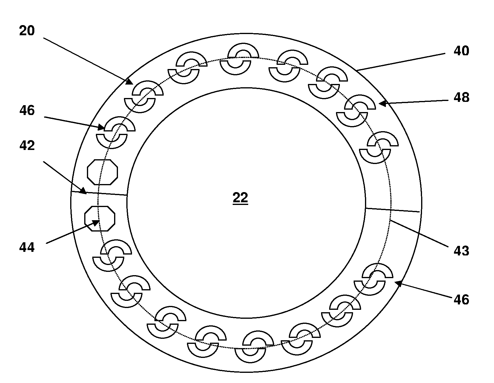
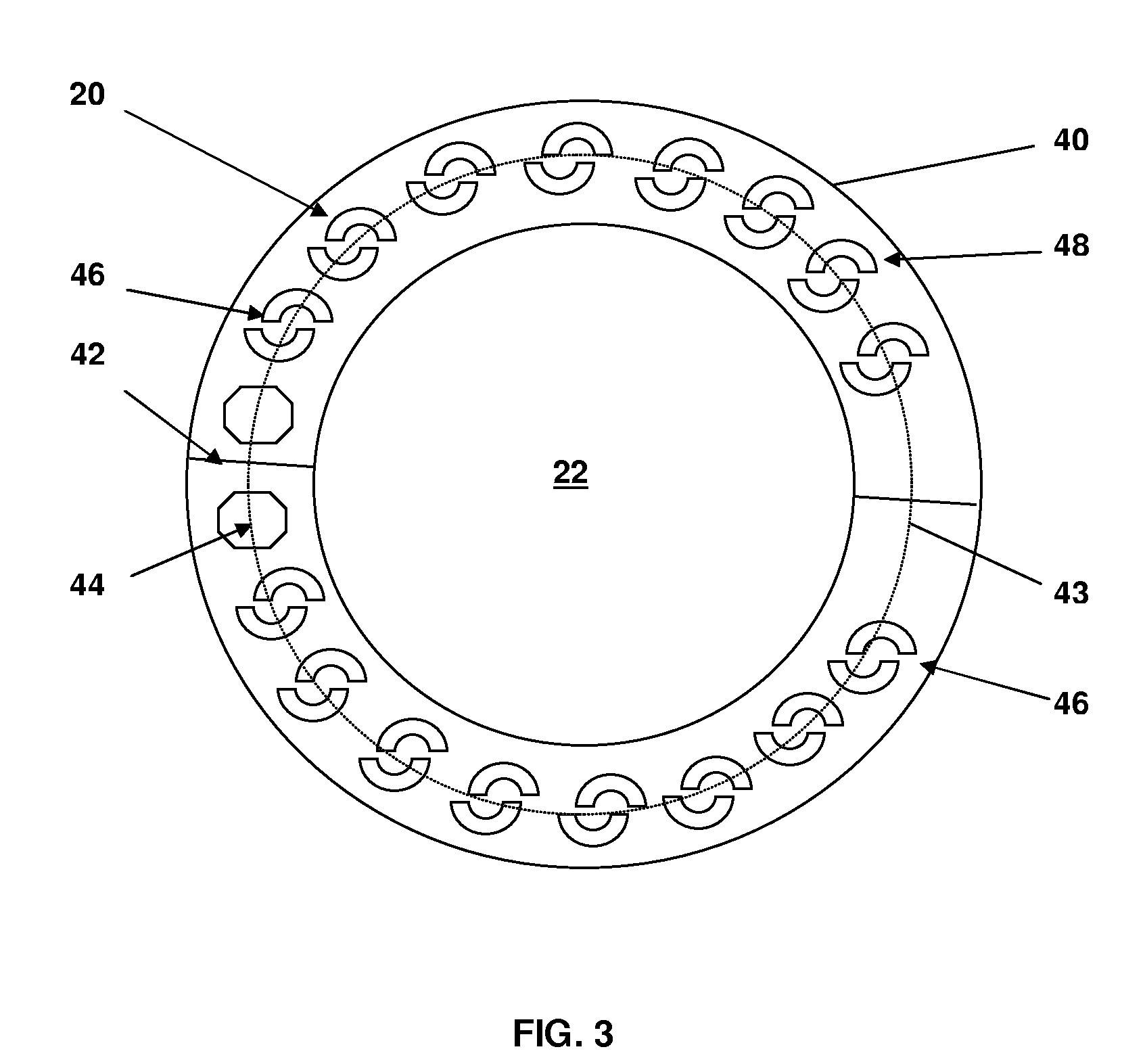
[0022]As shown in FIG. 3, an embodiment is illustrated in which burners 46 either side of the split line 42 are located further apart than burners 48 distant from the split line 42 by a factor of at least two, but preferably by at least four, but less than seven, and are preferably spaced such that the split line 42 is approximately equidistant from these burners 46. The separation distance used to determine these factors throughout this specification is measured along an imaginary central arc 43 passing approximately through the axis of each...


PUM


Abstract

A combustor arrangement for a gas turbine engine (31) has a split line (42) and a plurality of burners (20,37) arranged in an annular ring (40). The burners (46) of the combustor on either side of the split line (42) have a separation distance of at least two times the average separation distance between burners (48) distant from the split line (42).

Description

[0001]This application claims priority under 35 U.S.C. §119 to European patent application no. 08156297.7, filed 15 May 2008, the entirety of which is incorporated by reference herein.BACKGROUND[0002]1. Field of Endeavor[0003]The invention relates to the design of an annular combustor of a gas turbine engine. More specifically the invention relates to a combustor design with reduced carbon monoxide emissions.[0004]2. Brief Description of the Related Art[0005]A gas turbine engine to which this invention can be applied is shown in FIG. 1 and has the following elements. A compressor 21 compressing air, for use in a high-pressure combustion chamber 22 is fitted with premix burners 20, as well as for cooling. Partially combusted air from the high-pressure combustor 22 passes through a high-pressure turbine 23 before flowing further into a low-pressure combustion 24 chamber where combustion occurs by self-ignition. In this chamber fuel is added to unburnt air from the high-pressure combus...

Claims


Application Information

Patent Timeline
Patent Type & Authority Applications(United States)
IPC IPC(8): F23R3/42F02C7/24F23M20/00
CPCF23C2900/03003F23R3/10F23M20/005F23R2900/00014F23R3/50
Inventor EROGLU, ADNANRICCIUS, OLIVERKNAPP, KLAUSFLOHR, PETER
Owner ANSALDO ENERGIA SWITZERLAND AG
Why Eureka
Try Eureka