Aircraft with connection element for connecting a conduit system to cooling aggregates in aircraft cabins

a technology of connecting elements and aircraft, which is applied in the direction of branching pipes, mechanical equipment, transportation and packaging, etc., can solve the problems of inability to install above cross beams or main conduits of air conditioners in the supply chamber, large structural shape, and inability to install above cross beams or main conduits, etc., to achieve simple and reliable sealing, small installation height, and flexible

Inactive Publication Date: 2009-11-19
AIRBUS OPERATIONS GMBH
View PDF30 Cites 2 Cited by
  • Summary
  • Abstract
  • Description
  • Claims
  • Application Information

AI Technical Summary

Benefits of technology

[0007]According to an exemplary embodiment of the invention, an aircraft with a connection element of the above mentioned kind may be provided in that at least one fastening element for the fastening of the conduit element of the cabin chamber may be provided within the connection part. Thereby, on the one hand, may be effected that the connection part ends up with the separation part in a maximally flush manner. In other words, the connection element does not protrude from the separation element, so that a plane surface without stumble edges or the like may be ensured. Moreover, for example for pressure test purposes, the connection element may be provided with blind plug(s), that also do not protrude from the separation element into the cabin chamber. On the other hand, the connection elements according to an exemplary embodiment of the invention, due to their construction, may be sufficiently compact that only a small installation height may be necessary which may also allow for an installation above cross beams, air conditioner conduits or other construction elements within the supply chamber and below the separation element. Further, the exemplary embodiment of the invention may allow for a simple and reliable sealing between the upper deck and the lower deck.
[0008]According to an exemplary embodiment of the invention, a compact connection element may be provided which may allow for a secure and reliable feed-through of conduit elements via a separation element, and at the same time may be handled in an easy and comfortable manner.
[0009]For example, the connection part may have an inner thread at the side facing the cabin chamber. Thereby, a particularly tight, flexible and easily manageable fastening of the conduit element of the cabin chamber may be possible. Due to the only small opening in the bottom plate, a strengthening of the bottom plate may be omitted.
[0010]In an exemplary embodiment of the invention, a flange element may be assigned to the connection part, wherein the flange element may be disposed with respect to the free end facing the cabin chamber in a standing-back manner. Thereby, on the one hand, a simple and fast mounting may be ensured. On the other hand, by means of the flange element, an optimal sealing possibility for sealing with respect to humidity may be created between the upper deck and the lower deck.

Problems solved by technology

On the one hand, this has the disadvantage that a big structural shape is necessary, namely particularly a big installation height.
Thereby, an installation above cross beams or main conduits for the air conditioner in the supply chamber is not possible.
On the other hand, due to the excess length with respect to the bottom plate, the connection elements form an abutting edge, which presents a stumbling danger in the cabin chamber and complicates the mounting of a kitchen as well as the change of position of individual aggregates.
Moreover, the known connection elements have a sealing difficulty.
A further disadvantage is that the known connection elements require a very big insection in the bottom plate, which makes necessary a strengthening of the surrounding bottom plate.

Method used


Image

  • Aircraft with connection element for connecting a conduit system to cooling aggregates in aircraft cabins
  • Aircraft with connection element for connecting a conduit system to cooling aggregates in aircraft cabins
  • Aircraft with connection element for connecting a conduit system to cooling aggregates in aircraft cabins

Examples


Embodiment Construction

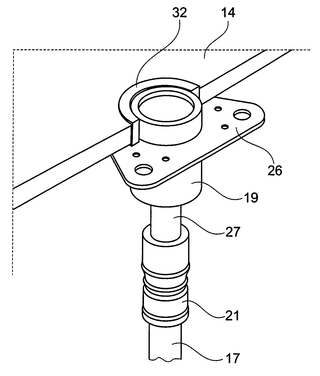
[0023]The connection elements shown in the figures serve as bottom feed-through connecting two conduit elements like, for example, tube elements, hose elements or socket elements with each other via a bottom plate.

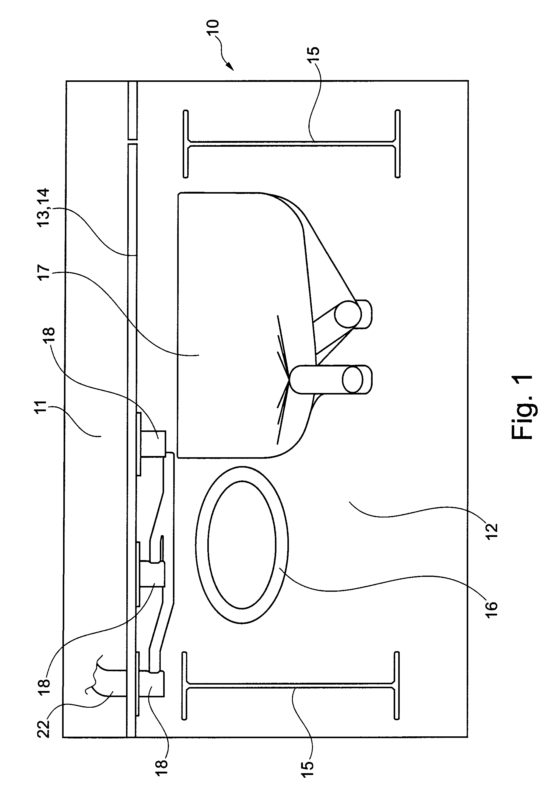
[0024]In FIG. 1, a section of a body 10 of an aircraft is schematically shown. Within the body 10, at least one cabin chamber 11 as well as at least one supply chamber 12 are provided. The cabin chamber 11 is separated or disjoined, respectively, from the supply chamber 12 by means of a separation element 13 which is provided as a bottom plate 14. Within the supply chamber 12, there are disposed different components, like, for example, crossbeams 15, traverse conduits 16 for supply of the air conditioner, as well as further conduit elements 17 serving, for example, for supplying cooling aggregates in the cabin chamber. For feeding through at least one conduit element 17 through the bottom plate 14, there is provided at least one connection element 18.

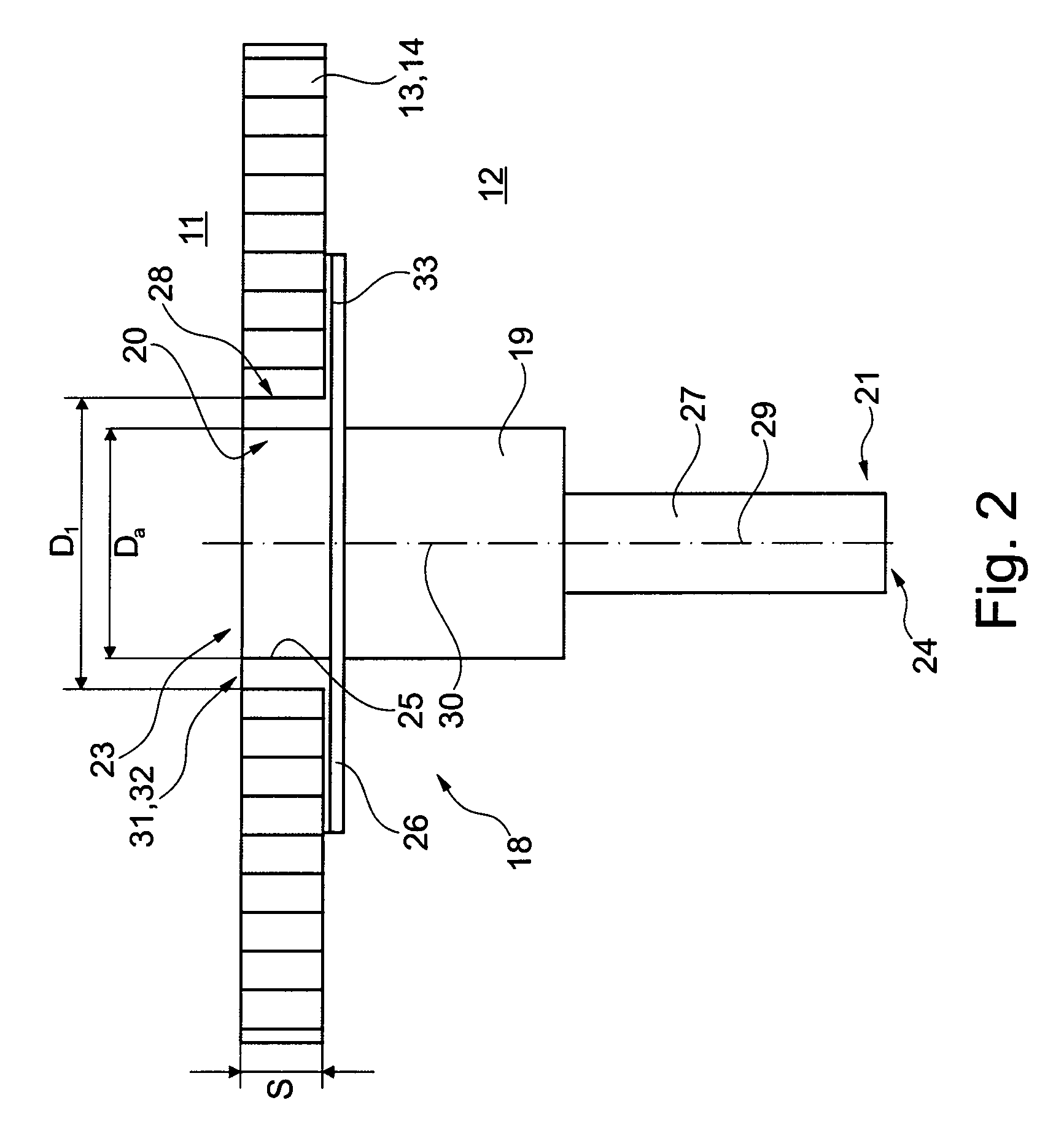
[0025]FIG. 2 illustrat...


PUM


Abstract

The invention relates to an aircraft with a connection element for connecting at least one first conduit element or the like positioned in a supply chamber of an aircraft with at least one second conduit element positioned in a cabin chamber of the aircraft, wherein supply chamber and cabin chamber are separated from each other by means of a separation element, substantially comprising a connection part comprising fastening elements for fastening the first and second conduit element.Known connection elements have the disadvantage that there occur sealing problems due to the fastening of the fastening element at the outside of the connection part at the end facing the cabin chamber. A further disadvantage is that the connection elements protrude into the cabin chamber and form stumble edges there.In that at least the fastening element for the fastening the conduit element of the cabin chamber is provided within the connection part, there may be realised a compact structural shape which does not protrude from the separating element into the cabin chamber, and which may in addition be reliably sealed.

Description

CROSS REFERENCE TO RELATED APPLICATIONS[0001]This is a divisional of U.S. Patent Application Ser. No. 11 / 123,910, filed May 6, 2005 in the name of Theo De Buhr and entitled CONNECTING ELEMENT FOR CONNECTING A CONDUIT SYSTEM TO COOLING AGGREGATES IN AIRCRAFT CABINS, the disclosure of which is incorporated by reference herein.FIELD OF THE INVENTION[0002]The invention relates to an aircraft with a connection element for connecting a first conduit element or the like positioned in a supply chamber of the aircraft with at least one second conduit element positioned in a cabin chamber of the aircraft, wherein supply chamber and cabin chamber are separated from each other by means of a separation part, substantially comprising a connection part comprising fastening element for fastening the first and second conduit elements.TECHNICAL BACKGROUND[0003]Connection elements of this kind are especially employed in aircraft construction. Aircraft usually have a cabin chamber in which at regular i...

Claims


Application Information

Patent Timeline
Patent Type & Authority Applications(United States)
IPC IPC(8): B64C1/00
CPCB64D11/04Y02T50/46F16L41/00Y02T50/40
Inventor DE BUHR, THEO
Owner AIRBUS OPERATIONS GMBH
Why Eureka
Try Eureka