Driving circuit for light emitting device with compensation mechanism and driving method thereof

a technology of compensation mechanism and driving circuit, which is applied in the direction of instruments, light sources, electrical devices, etc., can solve the problems of non-ideal circuit delay time and poor current accuracy, and achieve the effect of improving electromagnetic protection ability

Inactive Publication Date: 2009-11-19
LEADTREND TECH +1
View PDF4 Cites 42 Cited by
  • Summary
  • Abstract
  • Description
  • Claims
  • Application Information

AI Technical Summary

Benefits of technology

[0009]According to the above-mentioned embodiments, since the turn off time of the switch device is fixed such that the current ripple will not vary corresponding to different input voltages, the problem of poor current accuracy will not occur. Also, the operation frequency of the PWM circuit is not fixed, thus the circuit has better electromagne

Problems solved by technology

Moreover, since the discharging slope of the driving current is fixed, the problem of oscillation due to the switch device turning on before the ideal turn off ti

Method used


Image

  • Driving circuit for light emitting device with compensation mechanism and driving method thereof
  • Driving circuit for light emitting device with compensation mechanism and driving method thereof
  • Driving circuit for light emitting device with compensation mechanism and driving method thereof

Examples


Embodiment Construction

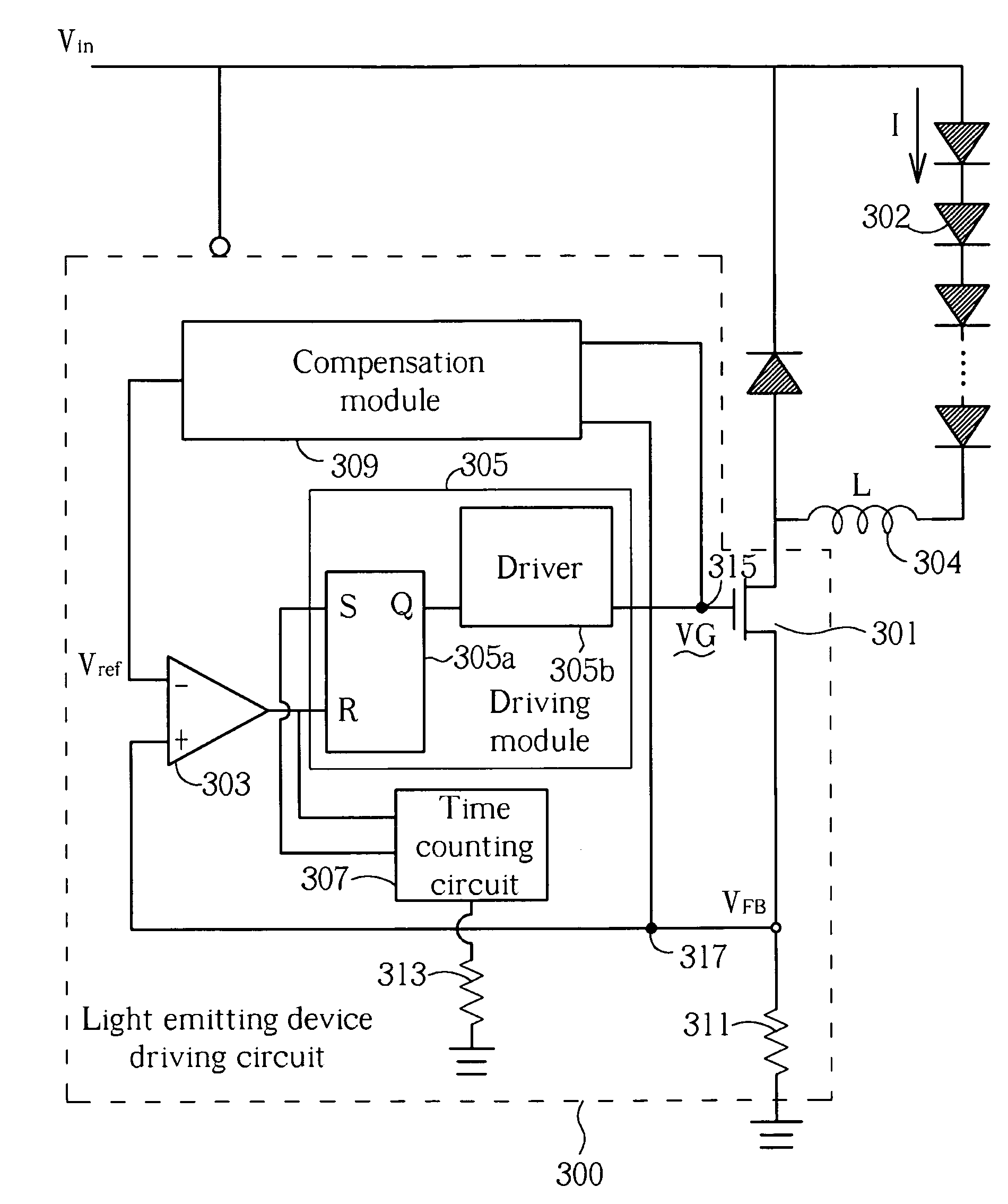
[0019]FIG. 3(a) is a circuit diagram illustrating a light emitting device driving circuit according to a preferred embodiment of the present invention. As shown in FIG. 3(a), the light emitting device driving circuit 300 is used for driving a light emitting device 302 (i.e. providing a driving current I to the light emitting device 302). Light emitting device driving circuit 300 includes a switch device 301, a comparator 303, a driving module 305, a time counting circuit 307, and a compensation module 309. The switch device 301 is a power transistor in this embodiment. The driving module 305 is used for generating a control signal VG that determines if the switch device 301 is on or off and controls the driving current I flowing through the light emitting device 302. Thus, the driving current I flowing through the light emitting device 302 is determined once the duty cycle of the control signal VG is determined. The current flowing through the resistor 311 can generate a feedback vo...


PUM


Abstract

A light emitting device driving circuit, includes: a switch device, a comparator, a driving module, a time counting circuit and a compensation module. The switch device is turned on or off according to a control signal for controlling a driving current flowing through the light emitting device. The comparator generates a comparison result according to a reference voltage and a feedback voltage corresponding to the driving current. The driving module generates the control signal according to the comparison result. The time counting circuit controls the driving module to turn on the switch device after the switch device turns off for a predetermined time. The compensation module detects a turn on time for the switch device and a delay time between the feedback voltage reaching the reference voltage value and the control signal varying correspondingly, and adjusts the reference voltage according to the turn on time and the delay time.

Description

BACKGROUND OF THE INVENTION [0001]1. Field of the Invention[0002]The present invention relates to a light emitting device driving circuit, and particularly relates to a light emitting device driving circuit, which has a compensation mechanism.[0003]2. Description of the Prior Art[0004]In a conventional driving circuit for a light emitting device (for example, a light emitting diode), a PWM (Pulse Width Modulation) circuit is utilized to control a switch device for controlling the current flowing through the light emitting device. Also, a comparator is utilized to compare a reference voltage with a feedback voltage proportional to the current to determine if the current should decrease or increase. Such a technique is a well-known controlling technique called peak-current controlling technique. This technique has many disadvantages, however. For example, the current ripple based on this structure substantially varies if input voltage varies and the input voltage of the light emitting...

Claims


Application Information

Patent Timeline
IPC IPC(8): H05B41/00
CPCH05B33/0818H05B45/3725
Inventor SHEN, YI-LUNWEI, DA-CHUN
Owner LEADTREND TECH
Why Eureka
Try Eureka