Supercharge Your Innovation With Domain-Expert AI Agents!

Locating a low-resistance fault in an electrical cable

a low-resistance, fault-locating technology, applied in the direction of fault location by conductor type, measurement device, instruments, etc., can solve the problem of difficult to determine the location of a fault, the cable is run in a difficult-to-reach area, and the normal performance of the cable is disrupted. problem, to achieve the effect of locating the fault, it is difficult, if not impossible in some cases

Inactive Publication Date: 2009-11-19
ACTERNA LLC
View PDF20 Cites 14 Cited by
  • Summary
  • Abstract
  • Description
  • Claims
  • Application Information

AI Technical Summary

Benefits of technology

[0013]In accordance with the invention there is provided a device for measuring a length lfault between a measurement point of a test cable having an inductance, and a low-resistance fault point of the test cable, wherein the device comprises an oscillator having an input and an output, for producing, at its output, electrical oscillations characterized by an osc

Problems solved by technology

It is quite common for cables to be run in difficult-to-reach areas, such as underground, underwater, under the floor or inside the walls of a house, or inside equipment that is difficult to take apart and then reassemble, such as an aircraft, for instance.
An electrical cable fault is a localized abrupt variation in a wire conductance or a wire-to-wire resistance that disrupts a normal performance of the cable.
Due to the mentioned limited accessibility of a cable, it is rather difficult, if not impossible in some cases, to determine the location of a fault by directly observing the cable.
The drawback of this method is that, in a frequent case of an underground or an over-the-air telegraph pole cable, a fault can be located quite far from the accessible end of the cable, so that a field test technician walking or driving along the cable and carrying with him the radio wave detector, has to travel sometimes for many thousands of feet before a location of the fault can be determined.
This method, called time-domain reflectometry (TDR), allows one to locate the fault more easily than the radio wave detection method mentioned above since no carrying of a detector along the cable is necessary; however, the TDR method, as well as a related method of frequency-domain reflectometry, requires complicated test equipment and specialized training of personnel servicing the test equipment.
A drawback of the method of Rogovin is the complexity of the data collection apparatus, as the complexity of the data processing and the data interpretation.
However, the method of Watkins has some limitations.
For example, using the capacitance method of Watkins, one cannot measure the distance to a low-resistance cable fault.
Yet, low-resistance faults commonly happen when, for example, a carpet installer inadvertently drives a carpet nail into a TV cable, phone line, or a network data cable, and causes, albeit not a perfect short, but a low-resistance fault in that cable.
Furthermore, we believe that the method of Watkins cannot be used to accurately measure a cable length between two end points in a cable network configured as a star network.

Method used


Image

  • Locating a low-resistance fault in an electrical cable
  • Locating a low-resistance fault in an electrical cable
  • Locating a low-resistance fault in an electrical cable

Examples


Embodiment Construction

[0029]While the present teachings are described in conjunction with various embodiments and examples, it is not intended that the present teachings be limited to such embodiments. On the contrary, the present teachings encompass various alternatives, modifications and equivalents, as will be appreciated by those of skill in the art.

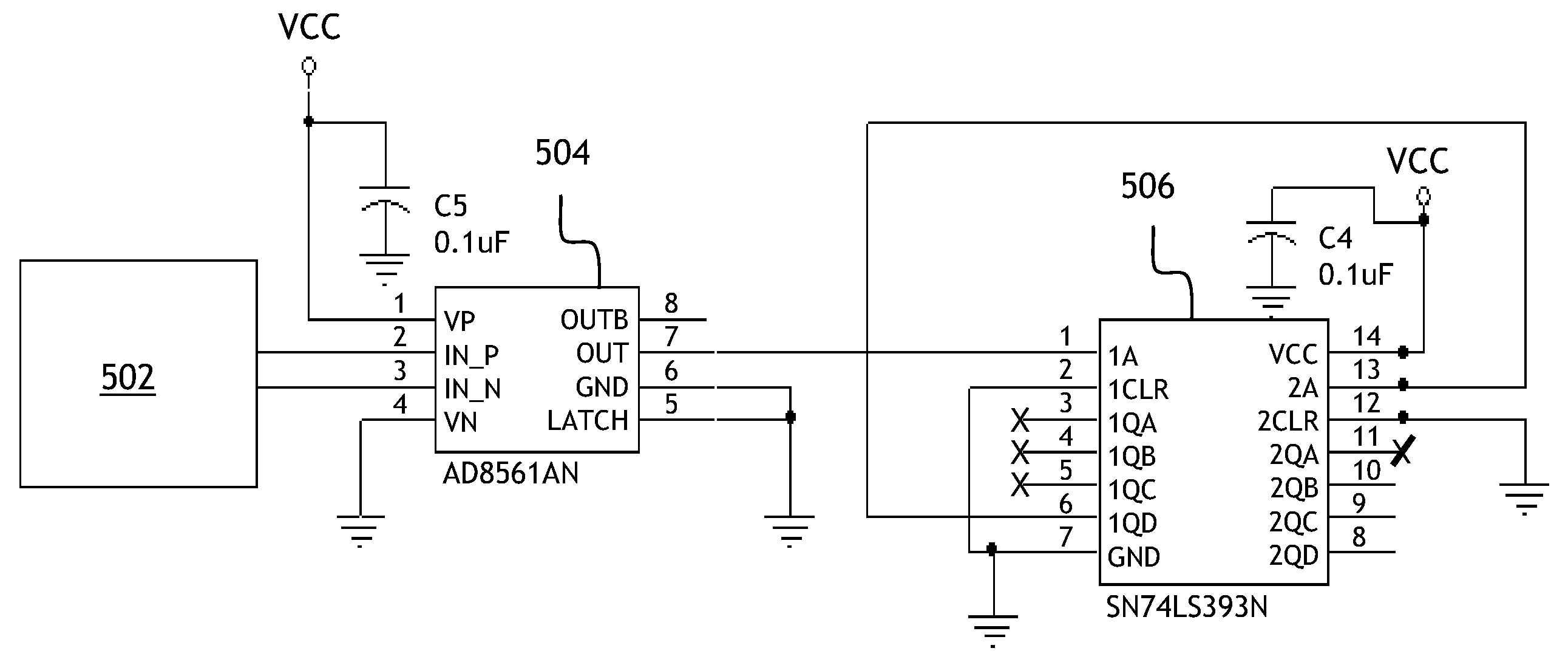
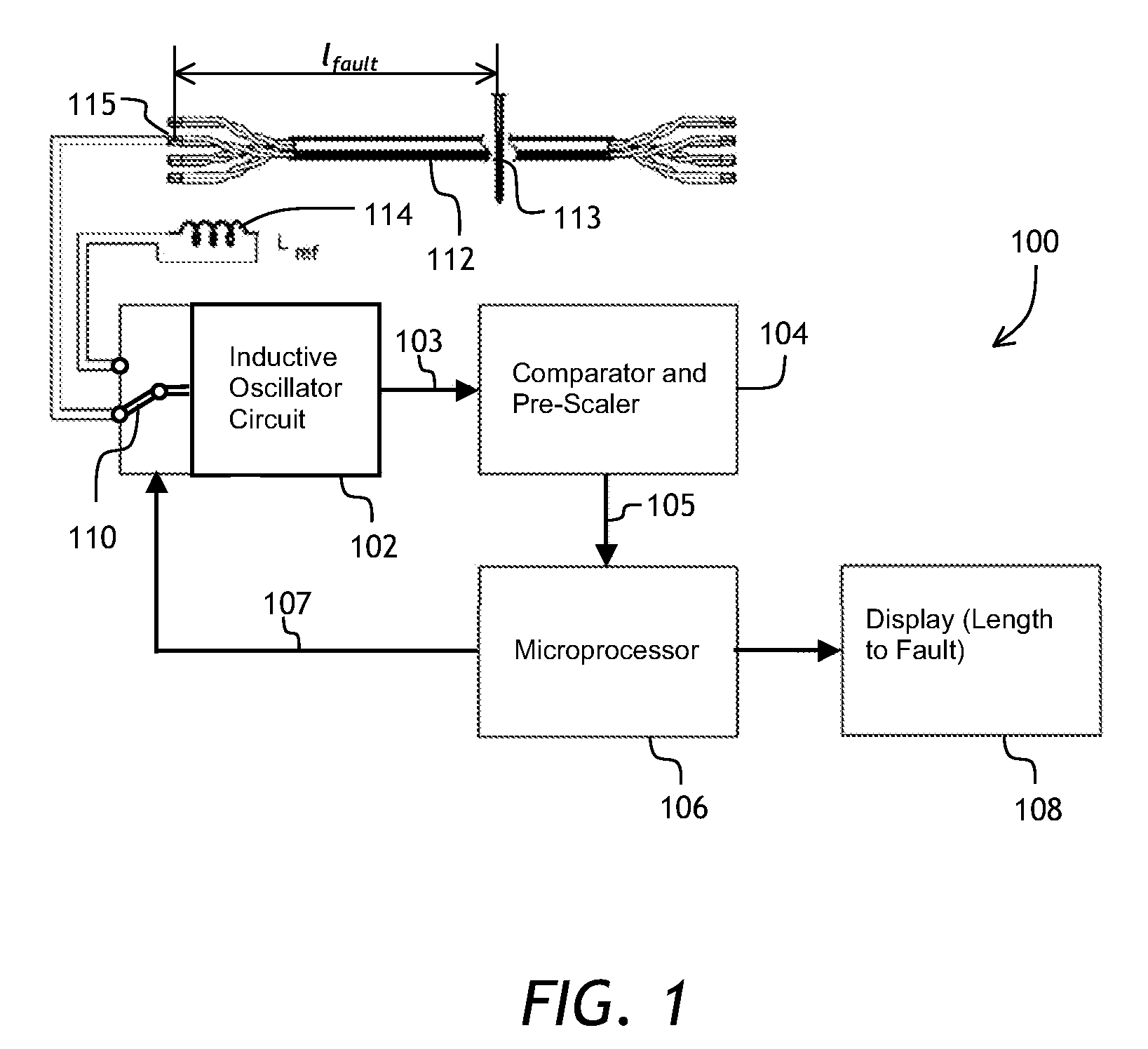
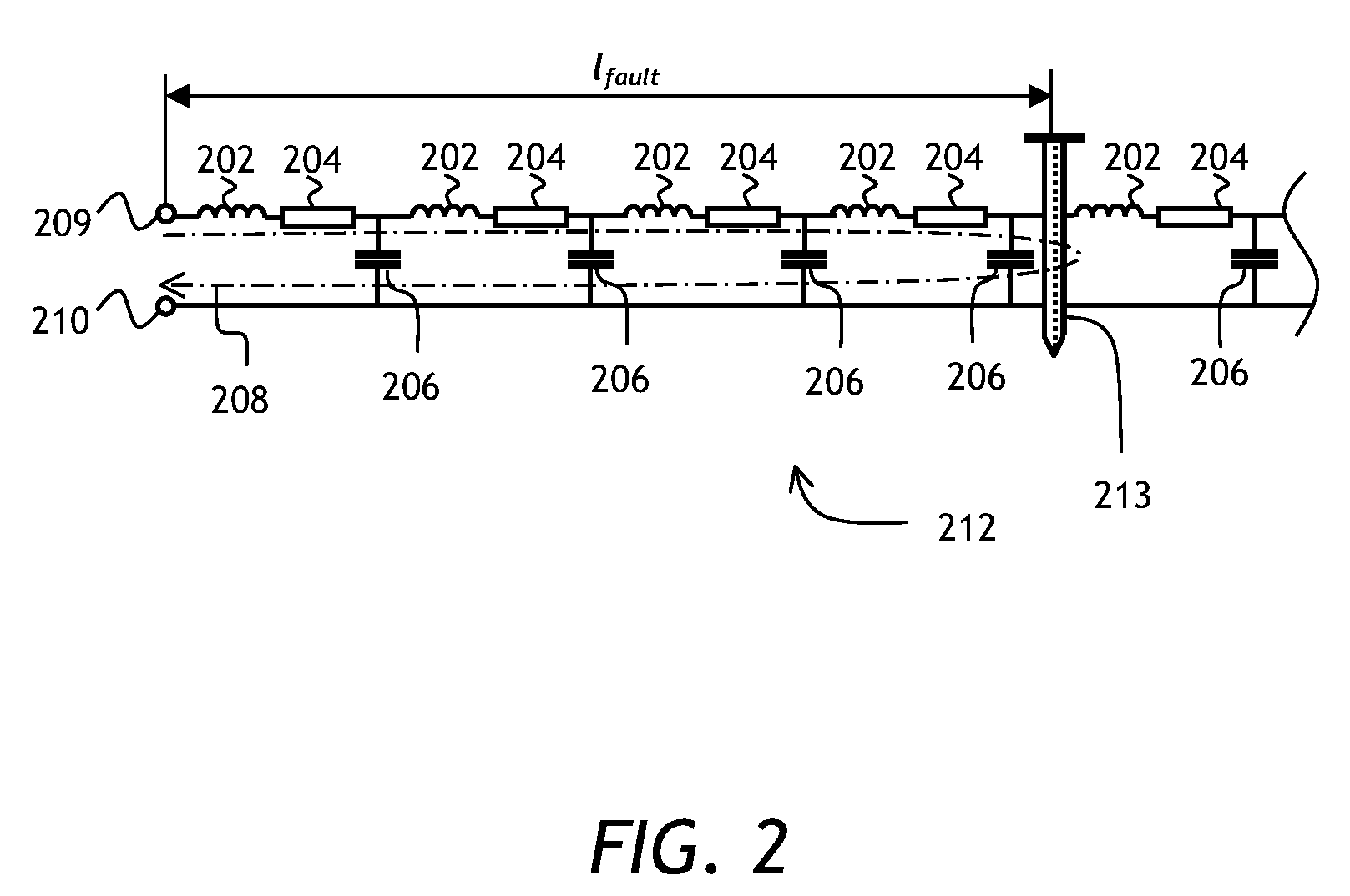
[0030]Referring to FIG. 1, a block diagram of an inductance based length-to-a-fault meter 100 of the present invention is shown comprising an inductive oscillator circuit 102, a comparator and pre-scaler circuit 104, a microprocessor 106, and a display 108. A switch 110 is used to switch an input of the oscillator 102 between: (a) an inductive faulted cable under test, or test cable 112 having a local low-resistance fault 113 symbolically shown as a nail driven through the cable 112; and (b) a reference inductor 114 having a reference inductance value of Lref. The fault 113 is located at a distance lfault from a measurement point 115. Herein the term “low...


PUM


Abstract

An inductance-based cable length-to-fault measurement device and method are described. The cable under test having a per-unit-length inductance is coupled to an inductance-sensitive oscillator, and the frequency of oscillations is evaluated using the following serially coupled modules: a comparator for digitizing the oscillator output, a pre-scaler for oscillation frequency down-conversion, and a microprocessor for counting pulses from the pre-scaler. To remove environmental and manufacturing tolerance dependencies, as well as a battery voltage dependence, the measured frequency of oscillations is compared to a frequency of oscillations of the oscillator having coupled thereto a reference inductor.

Description

[0001]The present invention claims priority from U.S. Patent Application No. 61 / 053,213 filed May 14, 2008, entitled “Determining Distance-To-Short Of A Coax, Data Or Communication Cable”, by Ng, which is incorporated herein by reference for all purposes.TECHNICAL FIELD[0002]The present invention is related to testing electrical cables, and in particular to a device and a method for determining a cable length to a low-resistance fault in the cable.BACKGROUND OF THE INVENTION[0003]An electrical cable is an insulated conductor or conductors used for transmitting electricity or communicating information. There are many types of electrical cables. A coaxial cable, a twisted-pair cable, a multi-wire cable, and a ribbon cable are examples of types of cables. It is quite common for cables to be run in difficult-to-reach areas, such as underground, underwater, under the floor or inside the walls of a house, or inside equipment that is difficult to take apart and then reassemble, such as an ...

Claims


Application Information

Patent Timeline
IPC IPC(8): G01R31/08
CPCG01R31/083
Inventor NG, ANTHONY C.
Owner ACTERNA LLC
Features
  • R&D
  • Intellectual Property
  • Life Sciences
  • Materials
  • Tech Scout
  • Unparalleled Data Quality
  • Higher Quality Content
  • 60% Fewer Hallucinations
Learn More