
Transmission path quality measuring device, communication system, quality measurement method, and quality measuring program

a technology of quality measurement and transmission path, applied in the field of transmission path quality measurement device, communication system, quality measurement method, quality measurement program, can solve problems such as the quality of the network that connects those devices, and achieve the effect of high reliability and accuracy

Inactive Publication Date: 2009-11-19
NEC CORP
View PDF20 Cites 19 Cited by
  • Summary
  • Abstract
  • Description
  • Claims
  • Application Information

AI Technical Summary

Benefits of technology

The present invention relates to a quality measuring device for measuring the communication quality of a network, such as a network used for transmitting data. The device includes a quality measuring unit that measures the communication quality of the network, an observation time calculating unit that calculates the time required for maintaining measurement accuracy, and a measurement start control unit that causes the quality measuring unit to start measurement at the calculated observation time. The device can easily compare results obtained at different times and can be used in both passive-type and active-type quality measuring operations. The invention aims to provide a more reliable and accurate measure of network quality and to facilitate comparison of results obtained at different times.

Problems solved by technology

In a case where a device performs communications with another device, there is often a problem with the quality of the network that connects those devices.

Method used


Image

  • Transmission path quality measuring device, communication system, quality measurement method, and quality measuring program
  • Transmission path quality measuring device, communication system, quality measurement method, and quality measuring program
  • Transmission path quality measuring device, communication system, quality measurement method, and quality measuring program

Examples


first embodiment

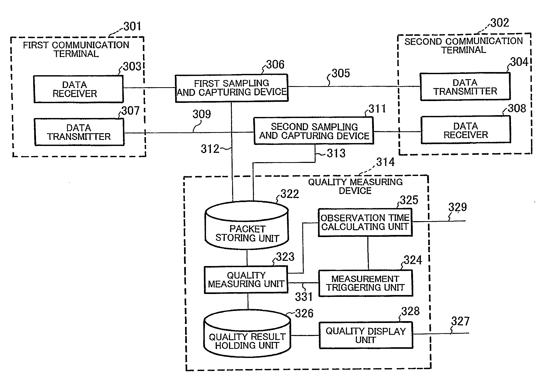
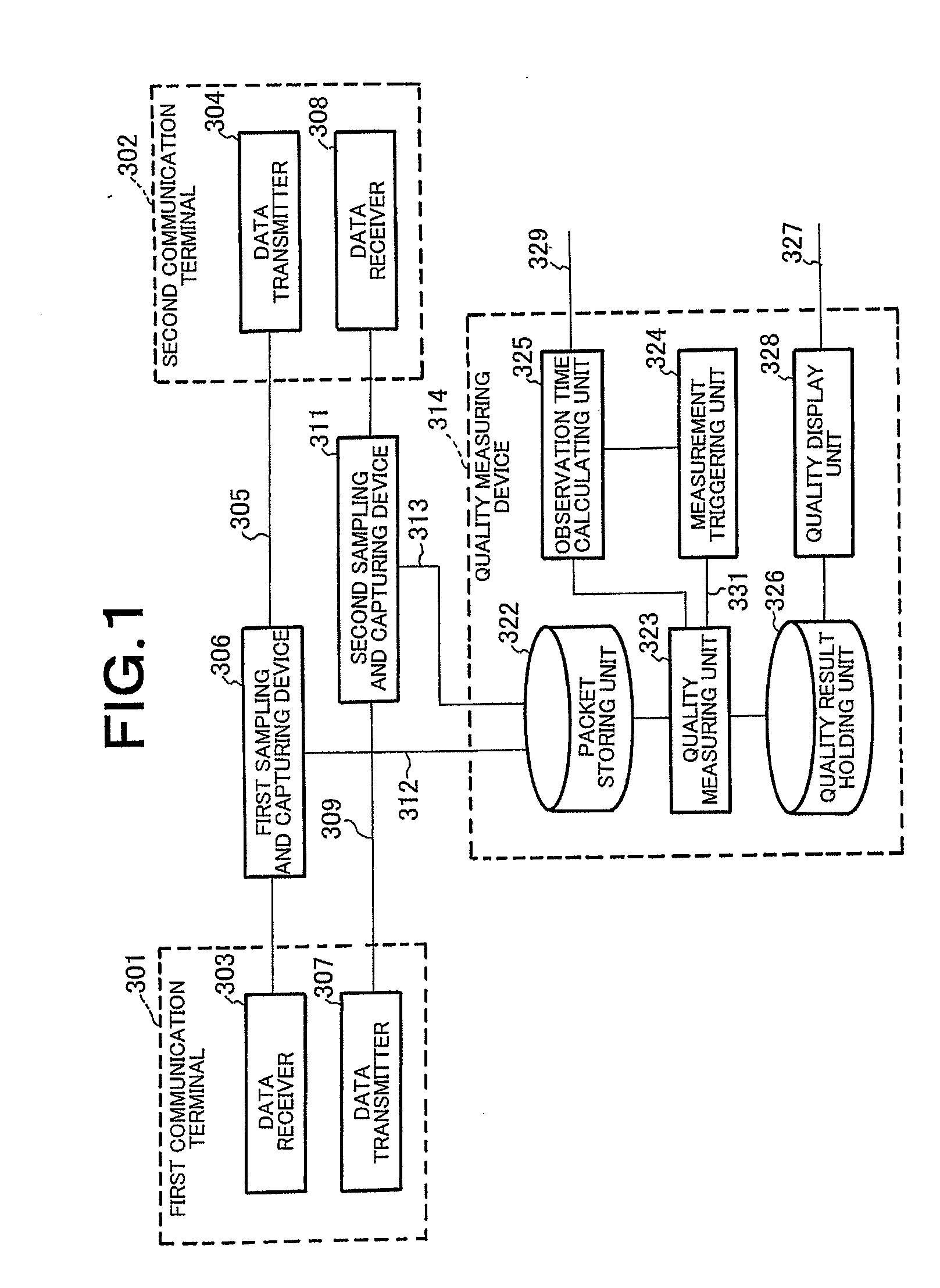
[0171]FIG. 1 shows the structure of a communication system that can measure network quality in accordance with a first embodiment of the present invention. In this communication system, the quality of packet communications between a first communication terminal 301 and a second communication terminal 302 is measured. A first sampling and capturing device 306 is placed as a branching device on a communication link 305 connecting a data receiver 303 of the first communication terminal 301 and a data transmitting unit 304 of the second communication terminal 302. Also, a second sampling and capturing device 311 is placed as another branching device on a communication link 309 connecting a data transmitting unit 307 of the first communication terminal 301 and a data receiver 308 of the second communication terminal 302. Packets 312 and 313 that are obtained from the first and second sampling and capturing devices 306 and 311 and are subjected to measurement are input to the quality meas...

second embodiment

[0205]FIG. 3 illustrates the structure of a communication system that can measure the quality of a network in accordance with a second embodiment of the present invention. In this communication system, the quality of packet communications between a first communication terminal 501 and a second communication terminal 502 is measured. For ease of explanation, the quality measurement to be carried out on packets transmitted from a data transmitting unit 506 of the second communication terminal 502 to a data receiver 507 of the first communication terminal 501 is not shown in the drawings, and explanation of it is omitted here, as quality measurement is to be carried out on test packets 505 transmitted from a data transmitting unit 503 of the first communication terminal 501 to a data receiver 504 of the second communication terminal 502 via a network (not shown). The data transmitting unit 503 can transmit packets other than the test packets 505, and the data receiver 504 can receive p...

third embodiment

[0229]FIG. 5 illustrates the structure of a communication system in which network quality measurement is carried out in accordance with a third embodiment of the present invention. In this communication system, the quality of packet communications between a first communication terminal 701 and a second communication terminal 702 is measured. For ease of explanation, the quality measurement to be carried out on packets transmitted from a data transmitting unit 706 of the second communication terminal 702 to a data receiver 707 of the first communication terminal 701 is not shown in the drawings, and explanation of it is omitted here, as quality measurement is to be carried out on test packets 705 transmitted from a data transmitting unit 703 of the first communication terminal 701 to a data receiver 704 of the second communication terminal 702. The data transmitting unit 703 can transmit packets other than the test packets 705, and the data receiver 704 can receive packets other than...


PUM


Abstract

The present invention provides a communication quality measuring device, a communication quality measurement method, and a communication quality measuring program by which the reliability and accuracy of the results of measurement carried out on a transmission path are improved, and comparisons between the results of measurement at one time and the results of measurement at another time or between one flow and another flow are made easier.The communication quality measuring device includes: a quality measuring unit (734) that measures the communication quality of a transmission path, based on data being transmitted through the transmission path; an observation time calculating unit (738) that calculates a time interval for securing an observation time for the quality measuring unit (734); and a measurement triggering unit (736) that causes the quality measuring unit (734) to start measurement at the time interval calculated by the observation time calculating unit (738). The observation time is the time required for maintaining predetermined measurement accuracy in the communication quality measured by the quality measuring unit (734). The data are the data to be transmitted for test to the transmission path, for example.

Description

TECHNICAL FIELD[0001]The present invention relates to a quality measuring device that measures the communication quality of a transmission path such as a network, and to a communication system, a quality measurement method, and a quality measuring program for guaranteeing accuracy of the communication quality on the network.BACKGROUND ART[0002]In a case where a device performs communications with another device, there is often a problem with the quality of the network that connects those devices. In this specification, “the quality of a network” represents a throughput as an effective speed, the amount of packet loss in transmitted packets, a packet loss rate, a delay time caused in transmission, a jitter as a variation of the time required for a packet arrival, a RTT (Round Trip Time) as the time required for a packet traveling back and forth between a communication terminal and another communication terminal, or a packet delay distribution.[0003]There have been suggestions for net...

Claims


Application Information

Patent Timeline
Patent Type & Authority Applications(United States)
IPC IPC(8): H04L12/26H04B17/00H04L69/40H04M3/00H04M3/26
CPCH04L12/2697H04L43/50H04L43/0829H04L43/0811
Inventor YAMASAKI, YASUHIRO
Owner NEC CORP
Learn More