Drive facility

Inactive Publication Date: 2009-11-19
SIEMENS AG
View PDF16 Cites 8 Cited by
  • Summary
  • Abstract
  • Description
  • Claims
  • Application Information

AI Technical Summary

Benefits of technology

[0012]It has also proven advantageous for the motor on the side of the motor facing the bearing not to have a bearing for mounting the engine shaft inside the motor. The components needed to assemble the motor can herewith be reduced.
[0013]It has also proven advantageous for the motor, on the side of the motor facing away from the bearing, to have a loose bearing for mounting the engine shaft. Since the bearing arranged outside the motor can bear axial forces, the bearing needed to mount the engine shaft can be embodied as a loose bearing on the side of the motor facing away from the bearing.
[0014]It has also proven advantageous for the outer ring of the bearing to be connected to the stationary component of the motor by means of screws passing th

Problems solved by technology

The design of the conventional connection which can be realized by means of such coupling facilities between the engine shaft and the load shaft is, as already mentioned, complexly structured, resulting in a correspondingly

Method used


Image

  • Drive facility
  • Drive facility
  • Drive facility

Examples


Example

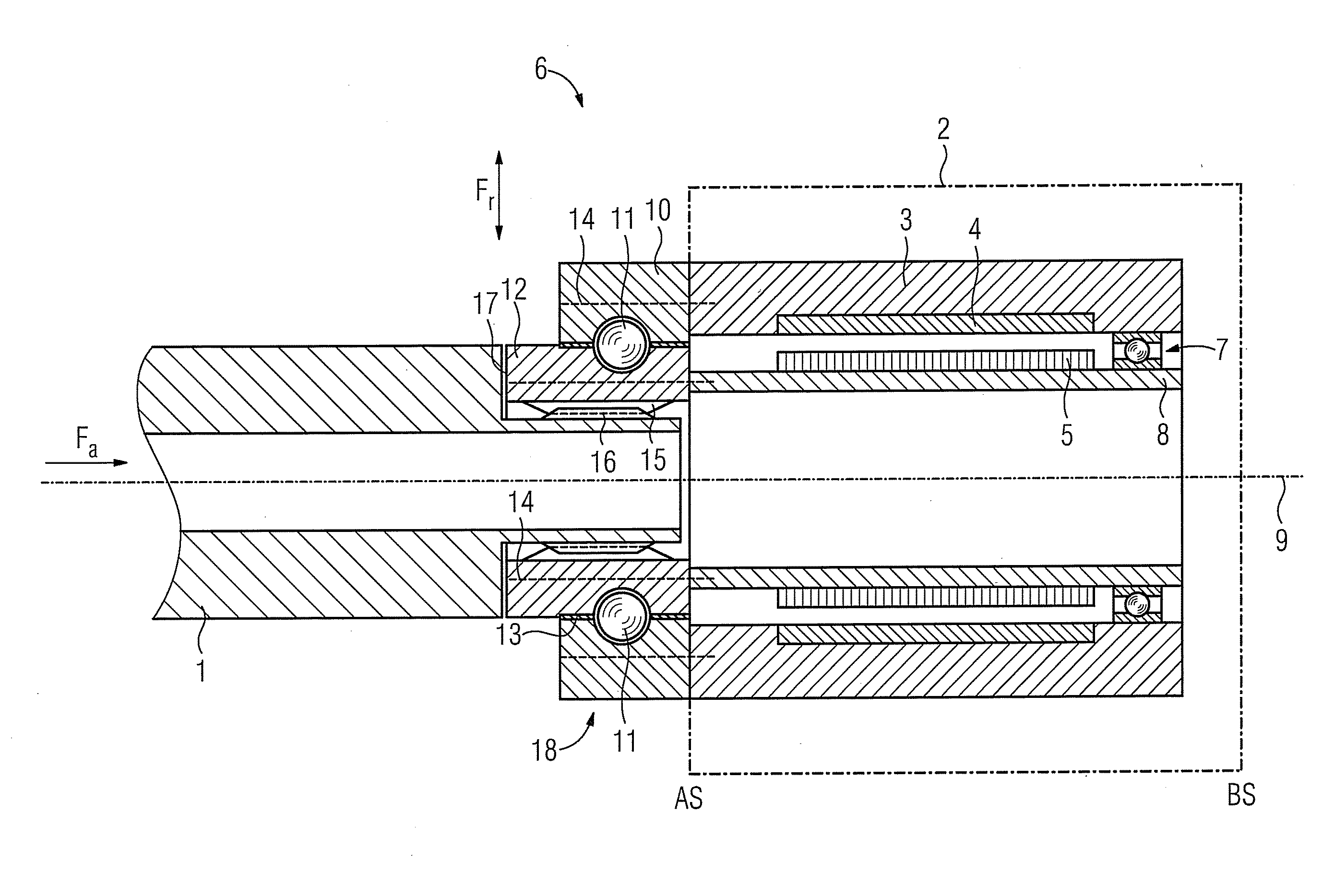
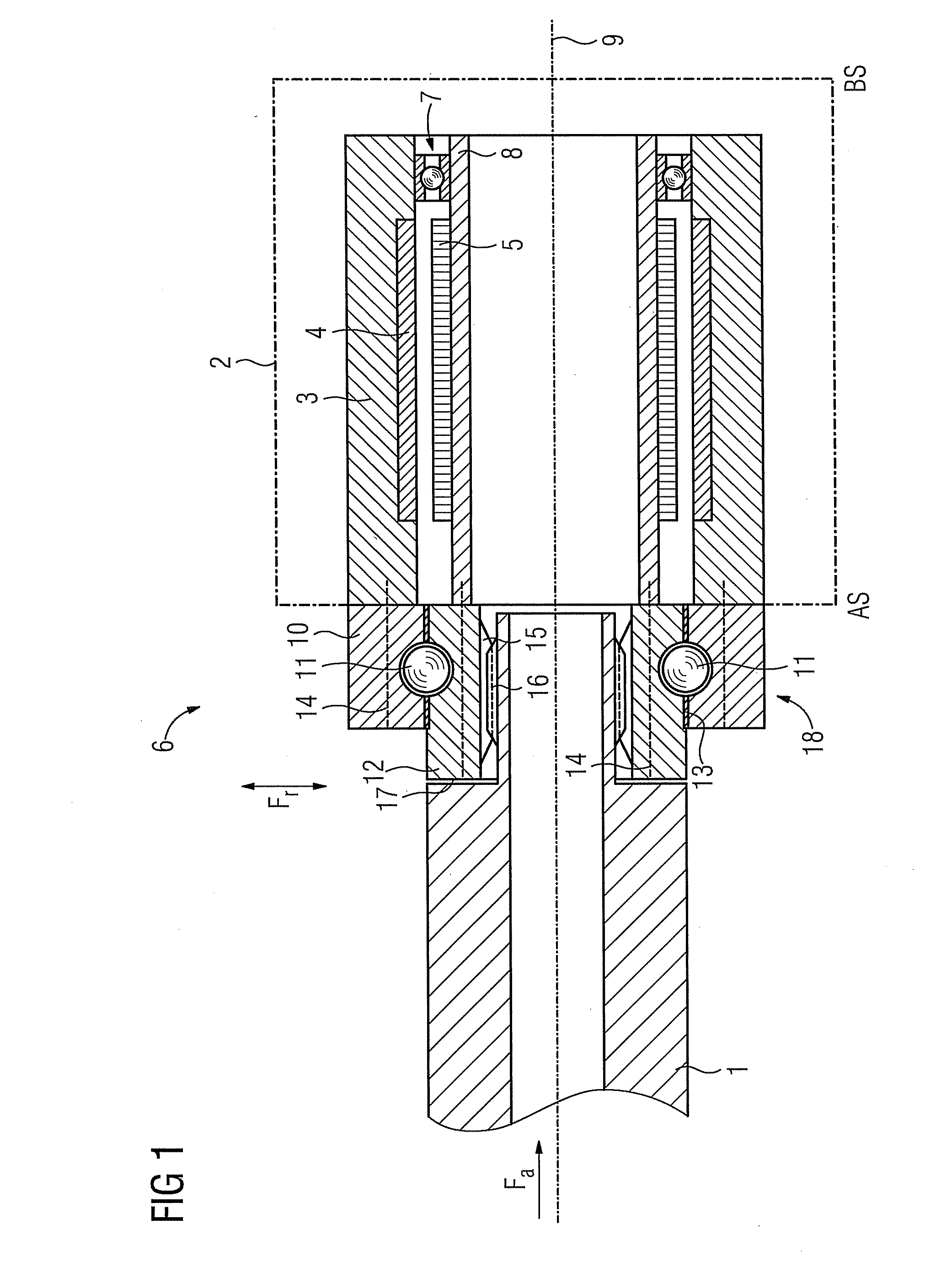
[0021]FIG. 1 shows a schematic representation of a drive facility 6, which is connected to a load shaft 1. The conventionally known coupling facility is realized in order to couple the load shaft 1 to the engine shaft 8 of a motor 2 in the form of a bearing 18. The coupling is realized as such using a bearing arranged outside the motor 2.

[0022]The bearing 18 has an outer ring 10, an inner ring 12 and several rolling elements 11, which are embodied as balls within the scope of the exemplary embodiment. The outer ring 10 is sealed off from the inner ring 12 by means of one individual or several seals 13, so that no lubricating liquid can leave the bearing from the rolling elements. Additional sealing components can herewith be dispensed with outside the bearing.

[0023]The outer and inner rings almost completely enclose the rolling elements. The bearing can transmit both an axial force Fa as well as a radial force Fr from the load shaft 1 onto the motor 2 in respect of an axis of rotati...


PUM


Abstract

A drive facility having an electric motor and a bearing arranged outside the motor for coupling a load shaft to a engine shaft of the electric motor is disclosed. The bearing has an outer ring, an inner ring and several rolling elements which are arranged between the outer ring and inner ring. An axial and a radial force are transmitted by the bearing from the load shaft onto the electric motor. The outer ring of the bearing is connected to a stationary component of the electric motor. The inner ring of the bearing is connected to a rotating component of the motor and is connectable to the load shaft. A torque generated by the motor is transmitted from the engine shaft to the inner ring.

Description

CROSS REFERENCE TO RELATED APPLICATIONS[0001]This application claims priority of European Patent Application No. 08009028.5 EP filed May 15, 2008, which is incorporated by reference herein in its entirety.FIELD OF INVENTION[0002]The invention relates to a drive facility.BACKGROUND OF INVENTION[0003]DE 103 57 884 A1 and DE 103 20 599 A1 disclose drive facilities for driving loads, in which a coupling is realized between a load shaft of a load to be driven and the engine shaft of an electrical motor with the aid of a complexly structured coupling facility. The design of the conventional connection which can be realized by means of such coupling facilities between the engine shaft and the load shaft is, as already mentioned, complexly structured, resulting in a correspondingly large installation size. Furthermore, coupling facilities integrated into the motor are also disclosed in DE 102 30 876 B3 for instance.[0004]Coupling facilities known from the prior art are disadvantageous in th...

Claims


Application Information

Patent Timeline
IPC IPC(8): F16C33/58
CPCF16C35/0635F16D1/076F16D1/10H02K7/083H02K5/1732H02K7/003F16D2001/103F16C19/16F16C2380/26
Inventor ECKEL, ULRICHSCHAUFELE, STEPHANWAIDER, SEBASTIAN
Owner SIEMENS AG
Why Eureka
Try Eureka