Dental implant drill apparatus and method

a technology for dental implants and drills, which is applied in the field of dental implant drills and methods, can solve the problems of inability of the drill bit itself to wobble or tilt abnormally, the prior art devices for positioning dental implants lack the ability to judge the vertical and horizontal relationship of the drill bit to the boney ridge, and the prior art devices lack the ability to do this. the effect of cutting and leveling the surfa

Inactive Publication Date: 2009-11-19
CHOE MIKE WANSIK
View PDF14 Cites 18 Cited by
  • Summary
  • Abstract
  • Description
  • Claims
  • Application Information

AI Technical Summary

Benefits of technology

[0013]A visible dot or mark may be formed on the outer periphery of the top of the upper portion of the device. During drilling, that mark spins, and when the drill bit is properly positioned the spinning mark defines a circle visible to the eye of the dentist in a plane parallel to the apparent plane of nearby existing teeth's upper surfaces. These nearby teeth might be two teeth adjacent to where the implant is intended to be installed. The dentist positions the drill bit so as to align the plane of the circle with the plane formed by the top surfaces of the patient's existing teeth. Thus, the dentist performing the implant operation is able to effectively “see” and sense both whether the drill bit is properly positioned with reference to the jawbone in which the implant is to be mounted and whether the drill bit is properly aligned with respect to existing teeth near the implant site.
[0014]The drilling is facilitated by use of cooling fluid, such as sterile isotonic water solution, admitted to the site of drilling. Its flow is dispersed by the presence of grooves formed in the top and side surfaces of the upper portion of the device. In one arrangement, a first set of top-surface grooves aligned with each other and extending across the top surface of the upper portion of the device are in perpendicular relation to and intersect a second set of top-surface grooves aligned with each other. Side-surface grooves are formed in the side surface of the upper portion such that any cooling fluid, typically water, admitted to any of the first and second set of top-surface grooves is encouraged to flow through the side-surface grooves. The top-surface grooves also perform the function of aiding alignment of the drill bit mount device with nearby teeth. The drill bit can be positioned so that one of the grooves is lined up with the nearby existing teeth.
[0016]In another arrangement of the device of the invention, the top of the drill bit above the upper portion of the device is removed which enables the remaining lower portion of the drill bit protruding from the bottom to be inserted into the pilot hole in the patient's jaw as a guide pin for X-ray evaluation of the pilot hole position and further enables the upper portion of the device to serve as a model of the spatial relationship between the existing teeth and the crown to be installed using the pilot hole as drilled.
[0017]Further advantage is achieved by use of a cutting tool on the bottom of the upper portion of the device of the invention to facilitate cutting and leveling the surface of the alveolar ridge and any tissue between the ridge and the cutting surface.

Problems solved by technology

Desirably, the drill bit itself is not allowed to wobble or tilt abnormally, particularly when drilling a pilot hole for implant surgery.
It is also recognized that dental implant pilot drill positioning devices of the prior art are deficient in their ability to accommodate a wide range of different widths of jawbone in which to mount an implant as well as a wide range of widths of spaces between existing teeth between which a new tooth is being implanted.
Such devices of the prior art also lack means for judging the vertical and horizontal relationship of the drill bit to the boney ridge.

Method used


Image

  • Dental implant drill apparatus and method
  • Dental implant drill apparatus and method
  • Dental implant drill apparatus and method

Examples


Embodiment Construction

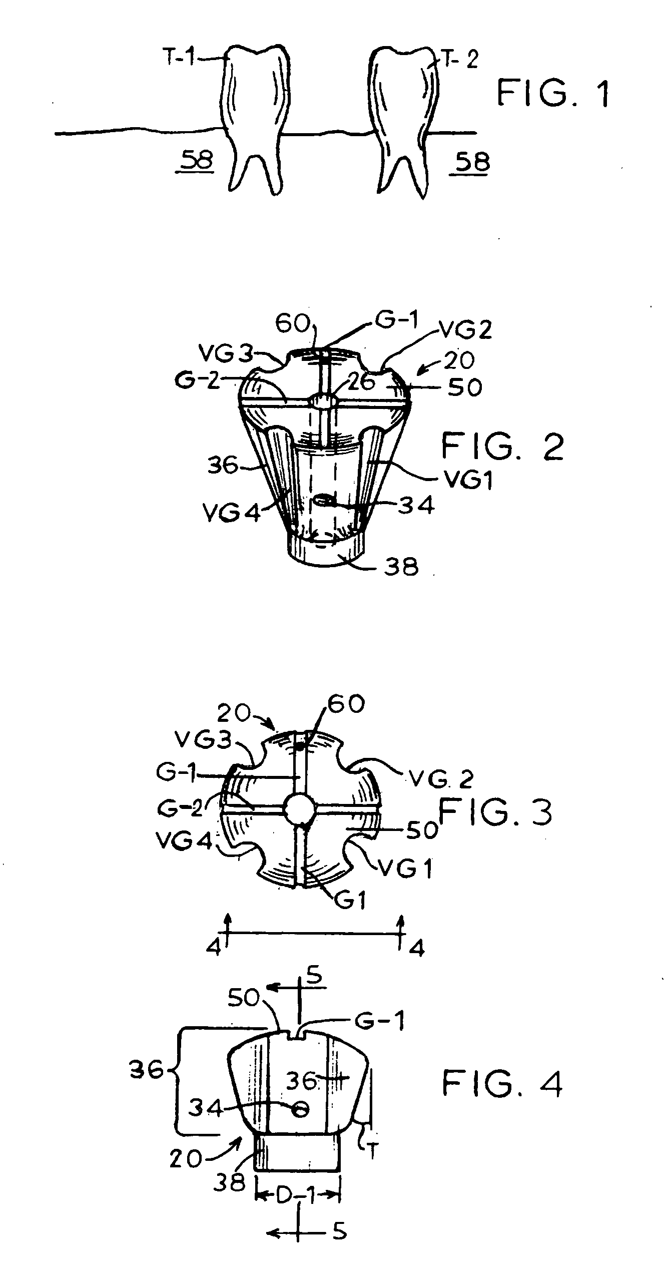
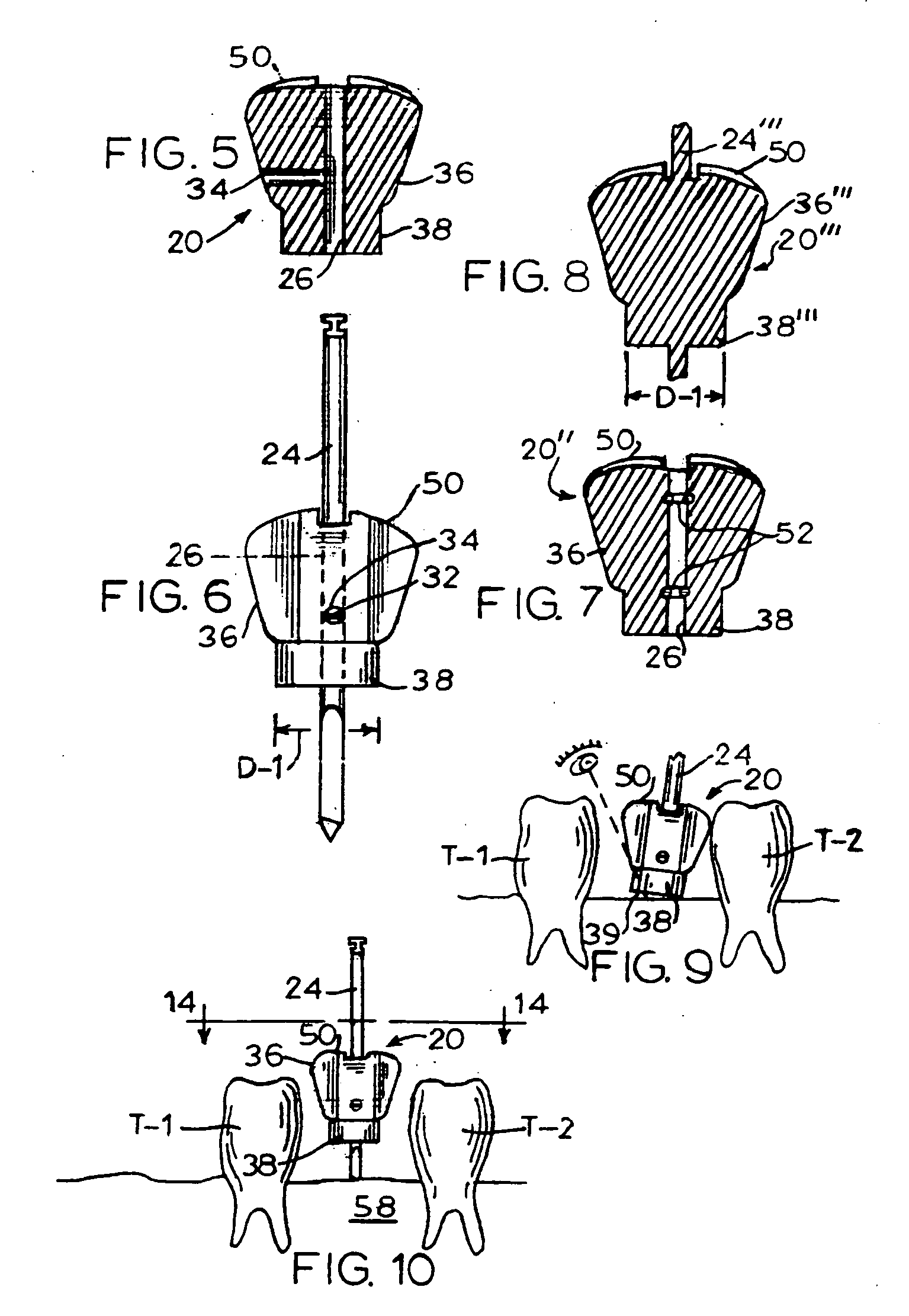
[0041]Referring initially to the construction of FIG. 6, drill bit 24 is slidably received in central hole 26 (FIG. 5) and is held in a selected position by means of a setscrew 32 (FIG. 6) mounted in a setscrew hole 34 (FIG. 5). Alternatively, the drill bit can be held by other fastening means, such as a screw, pin, wedge, key, adhesive or by friction. Preferably, the central hole passes through the center of mass of the drill bit mount device in order to avoid wobble when the drill bit and mount rotate during drilling. Drill bit 24 is powered by an appropriate power source or drive unit not shown in the drawings.

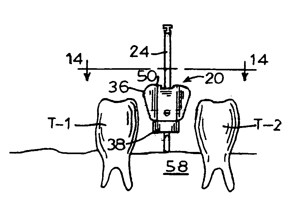
[0042]The dental implant drill bit mount device 20 (FIG. 2) is made in various sizes and constructions. A particular size is proposed according to the size of drill, the width of jawbone 58 (FIG. 1) available for implant insertion and the amount of space between the existing teeth T-1 and T-2 (FIG. 1) between which the implant MP (FIG. 17) is to be placed. The bottom diamet...


PUM


Abstract

A device is operatively associated with a drill used in connection with forming a hole in which a dental implant is to be installed. The device is made in multiple sizes suitable for accommodating differences in spacing between existing teeth between which one or more new prosthetic teeth are to be installed as well as accommodating differences in the bucco-lingual alveolar ridge width and the mesio-distal alveolar ridge length between the existing teeth where the implant is to be installed. The device is formed in such a way as to aid correct placement of the dental drill during implant surgery. The device permits the size of the proposed implant to be evaluated by visual comparison with the size of the selected implant site. The device further permits locating the dental implant pilot drill correctly so as to achieve successful implant placement.

Description

BACKGROUND OF THE INVENTION[0001]1. Field of the Invention[0002]The present invention relates to apparatus and methods for properly positioning a drill during dental implant surgery.[0003]2. Description of Related Art[0004]Replacement of missing natural teeth with teeth of similar shape and size fills an important need for those who have lost one or more of their teeth for one reason or another. A conventional practice for installing a prosthetic tooth involves drilling an initial vertical pilot hole in the jawbone of the patient followed in some instances after inspection of the initial pilot hole by drilling a larger pilot hole and in other instances by drilling a large vertical hole substantially concentric with the pilot hole and which is sized to receive the implant to which the prosthetic tooth will be attached. While implant surgery of the kind being referred to provides for replacement of multiple teeth as well as a single tooth, the replacement of a single tooth between two...

Claims


Application Information

Patent Timeline
Patent Type & Authority Applications(United States)
IPC IPC(8): A61C3/02A61C3/04
CPCA61C1/084
Inventor CHOE, MIKE WANSIK
Owner CHOE MIKE WANSIK
Why Eureka
Try Eureka