Ball joint assembly and method of making

Active Publication Date: 2009-11-26
FEDERAL MOGUL POWERTAIN LLC
View PDF34 Cites 20 Cited by
  • Summary
  • Abstract
  • Description
  • Claims
  • Application Information

AI Technical Summary

Benefits of technology

[0009]The invention includes an improved ball joint assembly having a reduced number of components six not including the ball stud, and assembly steps, part

Problems solved by technology

In the normal course of operation, ball joints are subjected to very high stresses.
Additionally, fewer components usually enable weight reduction.
In addition to the complexity noted with prior art b

Method used


Image

  • Ball joint assembly and method of making
  • Ball joint assembly and method of making
  • Ball joint assembly and method of making

Examples


Embodiment Construction

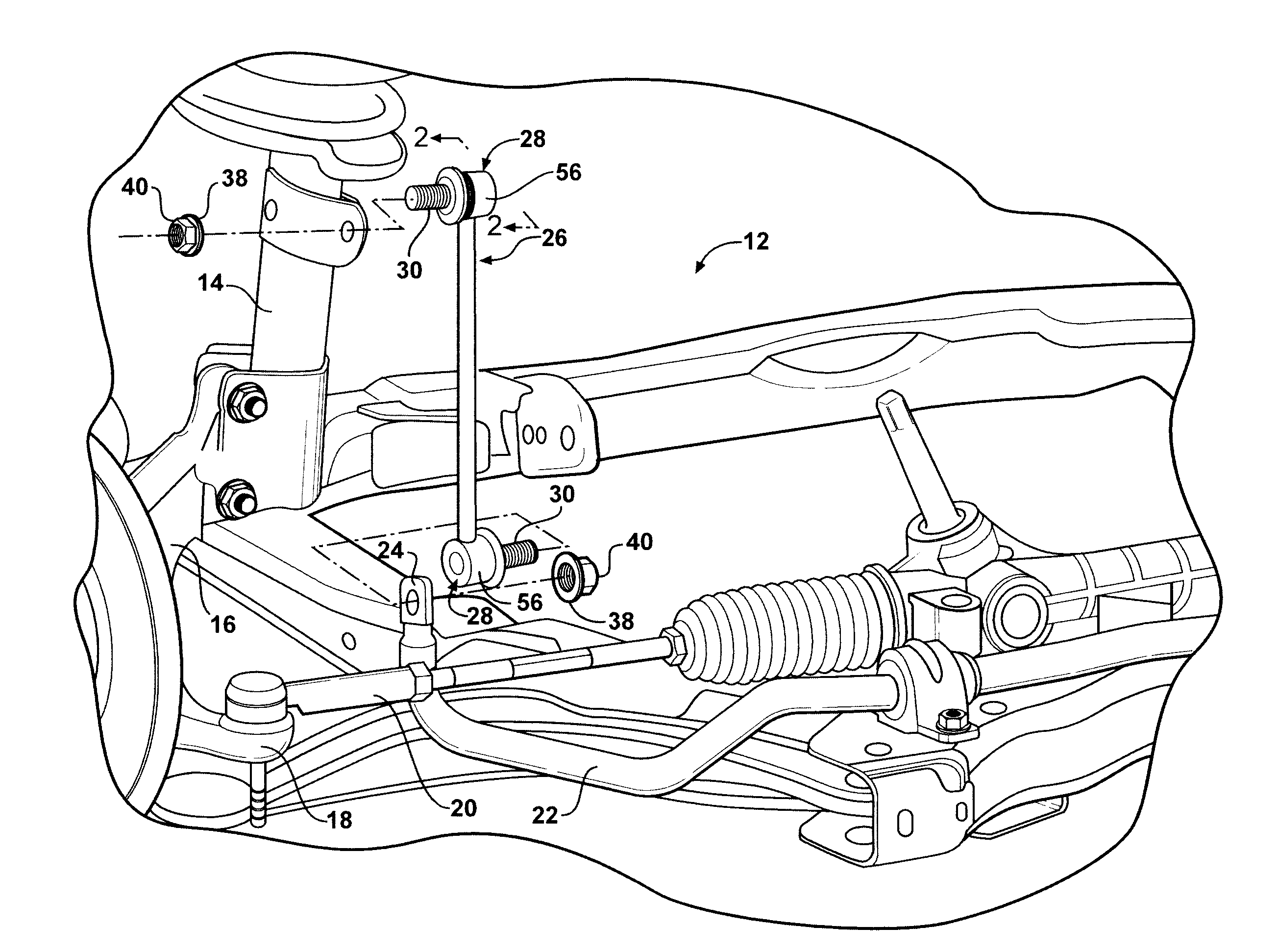
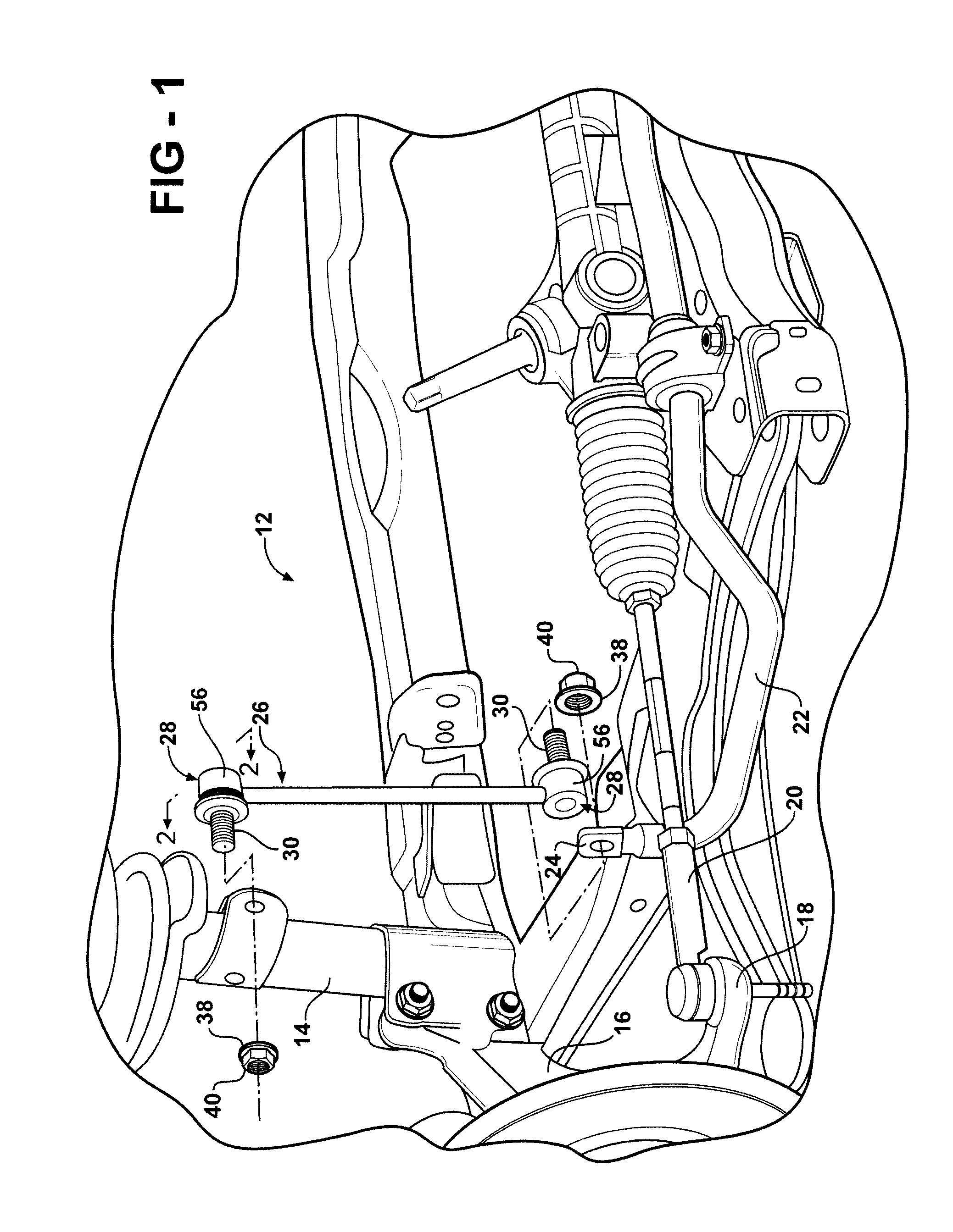
[0042]Referring to FIGS. 1-14 a vehicular steering and suspension assembly and associated components such as typically used in the front wheels of a motor vehicle is generally shown at 12 in FIG. 1. Although the front suspension system 12 is shown here comprising a MacPherson strut 14 type suspension system, it will be appreciated by those of skill in the art that the contemplated ball joint assemblies of the invention may find application in different control arm style suspension systems or in other forms and variations with equal effectiveness. For example, the invention may be deployed in steering or suspension linkages, frame member connections, and other articulating features, including all manner of stabilizer bars, tie rods and the like. Further, a ball joint assembly of the present invention may be utilized in all manner of non-vehicular applications which make use of an articulating joint.

[0043]Continuing with the illustrative application depicted in FIG. 1, the suspension ...


PUM

PropertyMeasurementUnit
Angleaaaaaaaaaa
Angleaaaaaaaaaa
Massaaaaaaaaaa

Abstract

A ball joint assembly includes a ball stud, a generally cylindrical bearing, a housing and a retainer which retains the bearing in the housing. The generally cylindrical bearing has an upper end, a lower end, a generally cylindrical exterior sidewall, an upper flange located between the upper end and a ring groove formed in the exterior sidewall, a lower flange proximate the lower end and extending outwardly from the exterior sidewall and a socket cavity that opens toward the lower end. The ball portion of the ball stud is engaged in and retained within the socket cavity. The bearing is secured within the housing in a bore within the housing by virtue of the working of the lower flange which is located within a counterbore of the housing and the upper flange and retainer located in the ring groove. Ball joints of the type described are able to resist a pull-out force of greater than 650 lbs and up to about 1200 lbs. They may also be sealed by incorporation of a dust boot which is attached to extends between the housing and the stud portion of the ball stud.

Description

BACKGROUND OF THE INVENTION[0001]1. Field of the Invention[0002]This invention relates to a ball and socket type joint of the type used in vehicular steering and / or suspension applications and, more particularly, toward a ball joint assembly having an plastic bearing insert and snap ring retainer.[0003]2. Related Art[0004]Ball joints are typically used in vehicular applications where three dimensional movement of a wheel or other component is required. The ball joint provides an articulated connection needed when a vehicle is turning and the suspension is accommodating movement over rough terrain or subjected to cornering forces. In the normal course of operation, ball joints are subjected to very high stresses. Thus, their components must be manufactured from strong, usually heavy, materials, such as steel. However, the recent emphasis on reducing vehicular weight is driving design criteria toward ball joints with reduced weight through the incorporation of materials such as variou...

Claims


Application Information

Patent Timeline
IPC IPC(8): F16C11/06
CPCF16C11/0633Y10T403/32737Y10T29/49664B23P2700/11B60G7/005B60G2204/416B60G2204/42B60G2204/4404B60G2206/82F16C11/0685
Inventor SCHMIDT, GEORGE R.BYRNES, TOMPARKER, GLEN
Owner FEDERAL MOGUL POWERTAIN LLC
Why Eureka
Try Eureka