Method and Device for Measuring Resistance Spot Welding Electrode Tips While Connected to a Robotic Welder

Inactive Publication Date: 2009-11-26
AUTOMATION SYST & DESIGN
View PDF13 Cites 20 Cited by
  • Summary
  • Abstract
  • Description
  • Claims
  • Application Information

AI Technical Summary

Benefits of technology

[0007]It is a general object to

Problems solved by technology

Such amperage values, flowing through a relatively high resistance, will create a lot of heat in a short time.
To make good resistance spot welds, it is necessary to have close control of the time the current is flowing and time as the controllable variable since current is economically impractical to control in most single impulse resistance spot welding applications.
This is less desirable in that the performance of the tip may have either degraded prior to the predetermi

Method used


Image

  • Method and Device for Measuring Resistance Spot Welding Electrode Tips While Connected to a Robotic Welder
  • Method and Device for Measuring Resistance Spot Welding Electrode Tips While Connected to a Robotic Welder
  • Method and Device for Measuring Resistance Spot Welding Electrode Tips While Connected to a Robotic Welder

Examples


Embodiment Construction

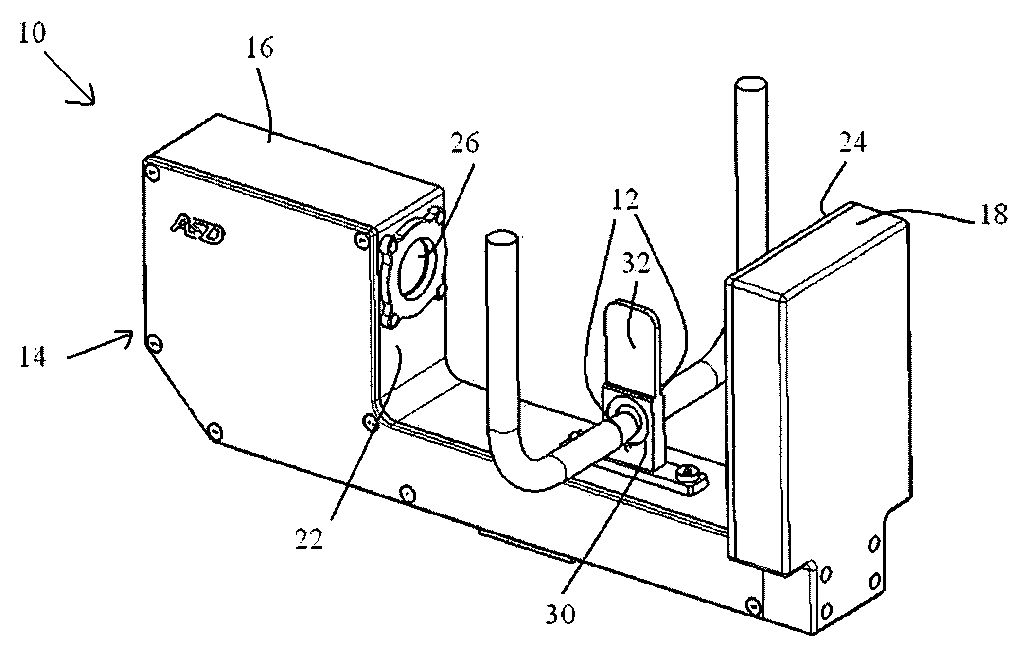
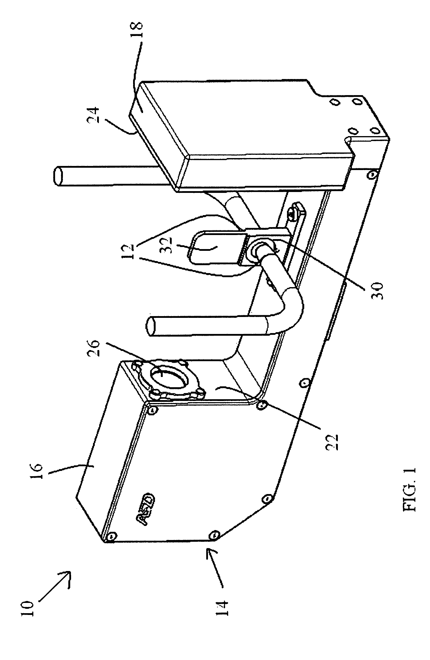
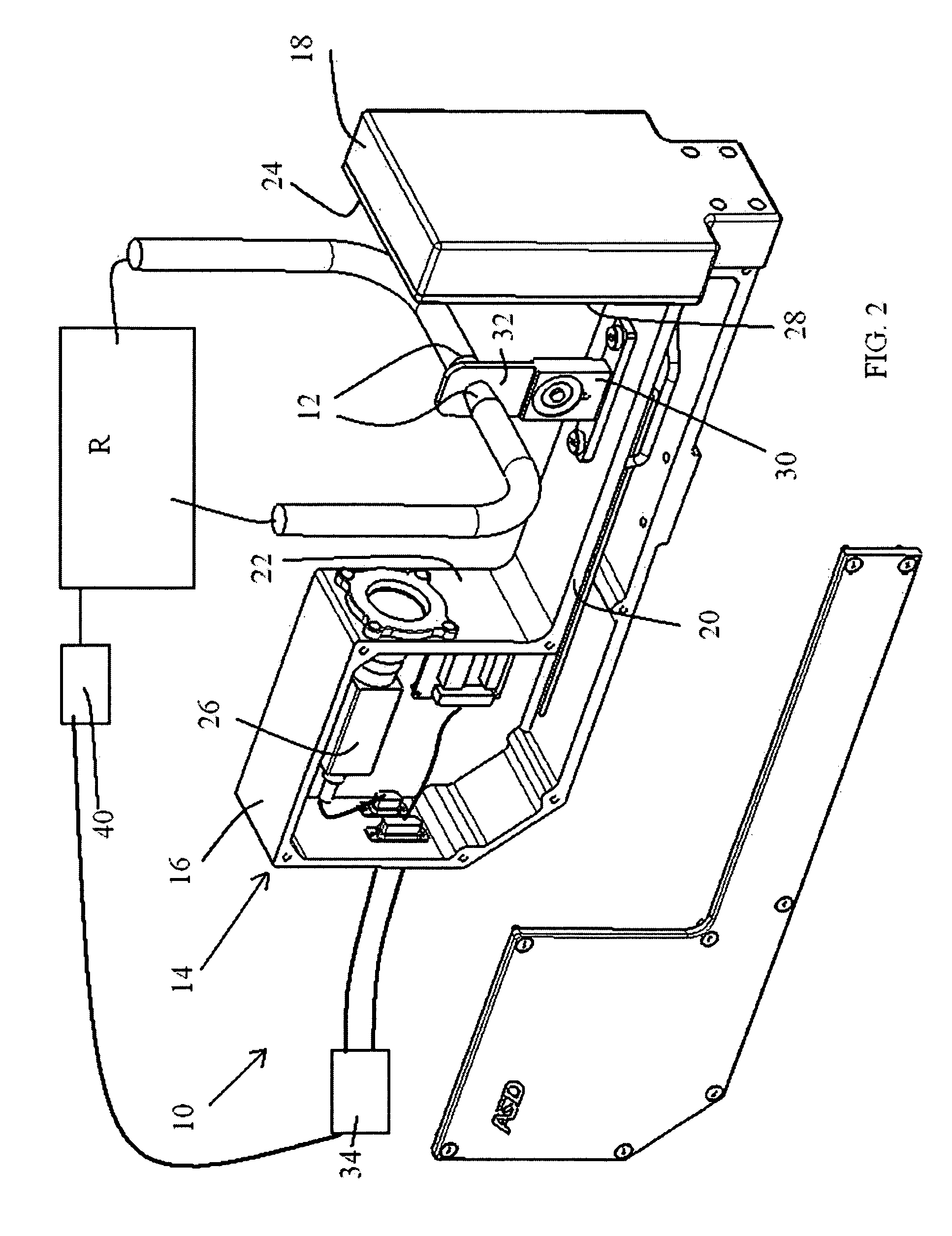
[0028]Referring now to the drawings, the welding electrode tip monitoring device of the present invention is generally designated by the numeral 10. The welding electrode tip monitoring device 10 can monitor welding electrode tips 12 while attached to a robotic welder which is generally designated here by letter R. The welding electrode tip monitoring device 10 can preferably be automatically employed as part of a robotic step with the robotic welder R.

[0029]The welding electrode tip monitoring device 10 can include a “U” shaped housing 14 having opposing housing portions 16 and 18 and transverse connecting portion 20. Housing portion 16 has a face 22 which opposes face 24 of housing portion 18. Housing portion 16 includes a vision CCD camera with lens 26 which is operably disposed through face 22. Housing portion 18 is operably equipped with and light panel 28 which is operably disposed on face 24 and serves a back light for tips 12 when being viewed by camera 26.

[0030]A load cell ...


PUM

PropertyMeasurementUnit
Forceaaaaaaaaaa
Diameteraaaaaaaaaa
Electrical resistanceaaaaaaaaaa

Abstract

A method and device for measuring a resistance spot welding electrode tip includes a welding electrode tip monitoring device for monitoring a welding electrode tip, the welding electrode tip monitoring device communicatively connected to a robotic welder equipped with electrode welding tips in a manner to be automatically employed as part of a robotic step with the robotic welder and is equipped with a mechanism for generating characteristic data of the welding electrode tips without having to remove the welding tips from the robotic welder.

Description

FIELD OF THE INVENTION[0001]The present invention relates to electrical resistance welding. More specifically, the invention relates to a device and method and device for measuring resistance spot welding electrode tips while connected to a robotic welder.BACKGROUND OF THE INVENTION[0002]Resistance spot welding depends on the resistance of the base metal and the amount of current flowing to produce the heat necessary to make the spot weld. Typically, several thousands of amperes are used in making the spot weld. Such amperage values, flowing through a relatively high resistance, will create a lot of heat in a short time. To make good resistance spot welds, it is necessary to have close control of the time the current is flowing and time as the controllable variable since current is economically impractical to control in most single impulse resistance spot welding applications.[0003]Proper pressures and intimate contact of the electrode tip and the base metal will tend to conduct hea...

Claims


Application Information

Patent Timeline
IPC IPC(8): B23K11/25B23K11/30
CPCB23K11/11B23K11/36B23K11/3072B23K11/3063
Inventor BOYD, SCOTT
Owner AUTOMATION SYST & DESIGN
Why Eureka
Try Eureka