Workpiece contact pads with elevated ring for restricting horizontal movement of terminals of IC during pressing

Inactive Publication Date: 2009-11-26
TEXAS INSTR INC
View PDF10 Cites 45 Cited by
  • Summary
  • Abstract
  • Description
  • Claims
  • Application Information

AI Technical Summary

Benefits of technology

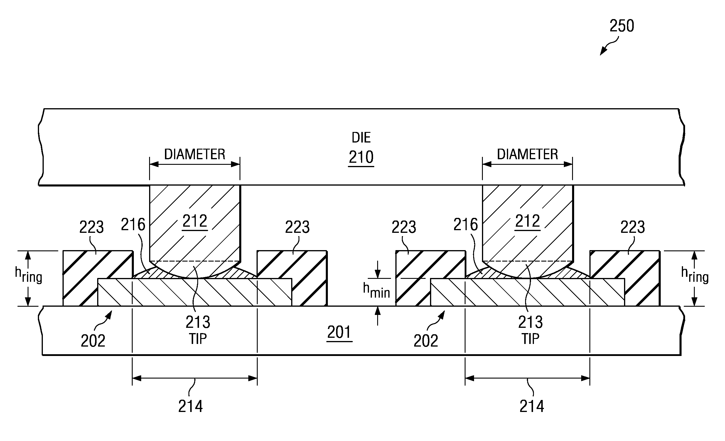
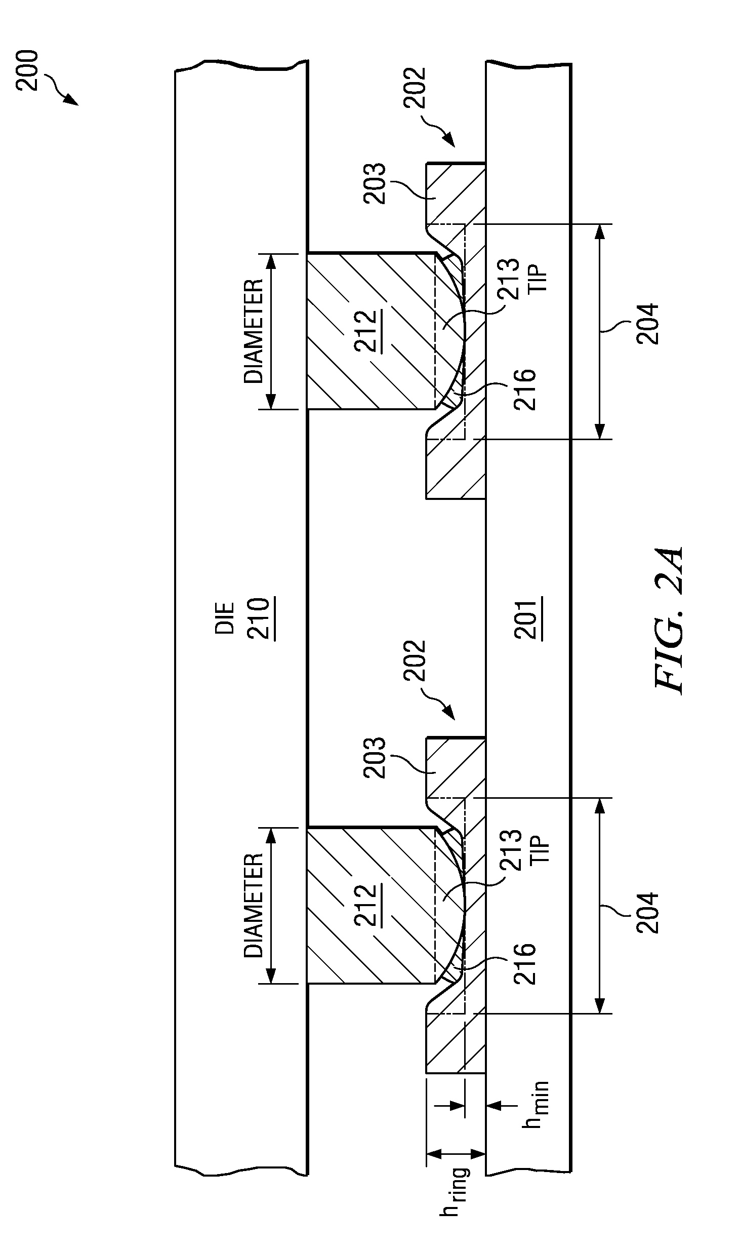
[0007]Embodiments of the invention generally provide a workpiece having workpiece contact pads that include an elevated ring and an indented bonding region with the ring. The Present Inventor's addition of elevated rings perimeters and indented bonding regions has been found to help trap the IC bonding conductor (e.g., solder bumps) therein and thus reduces the random horizontal movement of the IC from it

Problems solved by technology

Regarding the second bonding method described above, the Present Inventors have recognized that although the force applied by the heat plate to the IC die is generally in a vertical direction (e.g., along the z-axis; the out-of-plane direction) relative to the top surface of the workpiece (e.g., horizontally along the x-y plane; the in-plane direction), the IC die still tends to randomly shift horizontally (in-plane) relative to the workpiece surface and result in problems.
The distance of the horizontal shift can result in

Method used


Image

  • Workpiece contact pads with elevated ring for restricting horizontal movement of terminals of IC during pressing
  • Workpiece contact pads with elevated ring for restricting horizontal movement of terminals of IC during pressing
  • Workpiece contact pads with elevated ring for restricting horizontal movement of terminals of IC during pressing

Examples


Embodiment Construction

[0011]The present invention is described with reference to the attached figures, wherein like reference numerals are used throughout the figures to designate similar or equivalent elements. The figures are not drawn to scale and they are provided merely to illustrate the instant invention. Several aspects of the invention are described below with reference to example applications for illustration. It should be understood that numerous specific details, relationships, and methods are set forth to provide a full understanding of the invention. One having ordinary skill in the relevant art, however, will readily recognize that the invention can be practiced without one or more of the specific details or with other methods. In other instances, well-known structures or operations are not shown in detail to avoid obscuring the invention. The present invention is not limited by the illustrated ordering of acts or events, as some acts may occur in different orders and / or concurrently with o...


PUM


Abstract

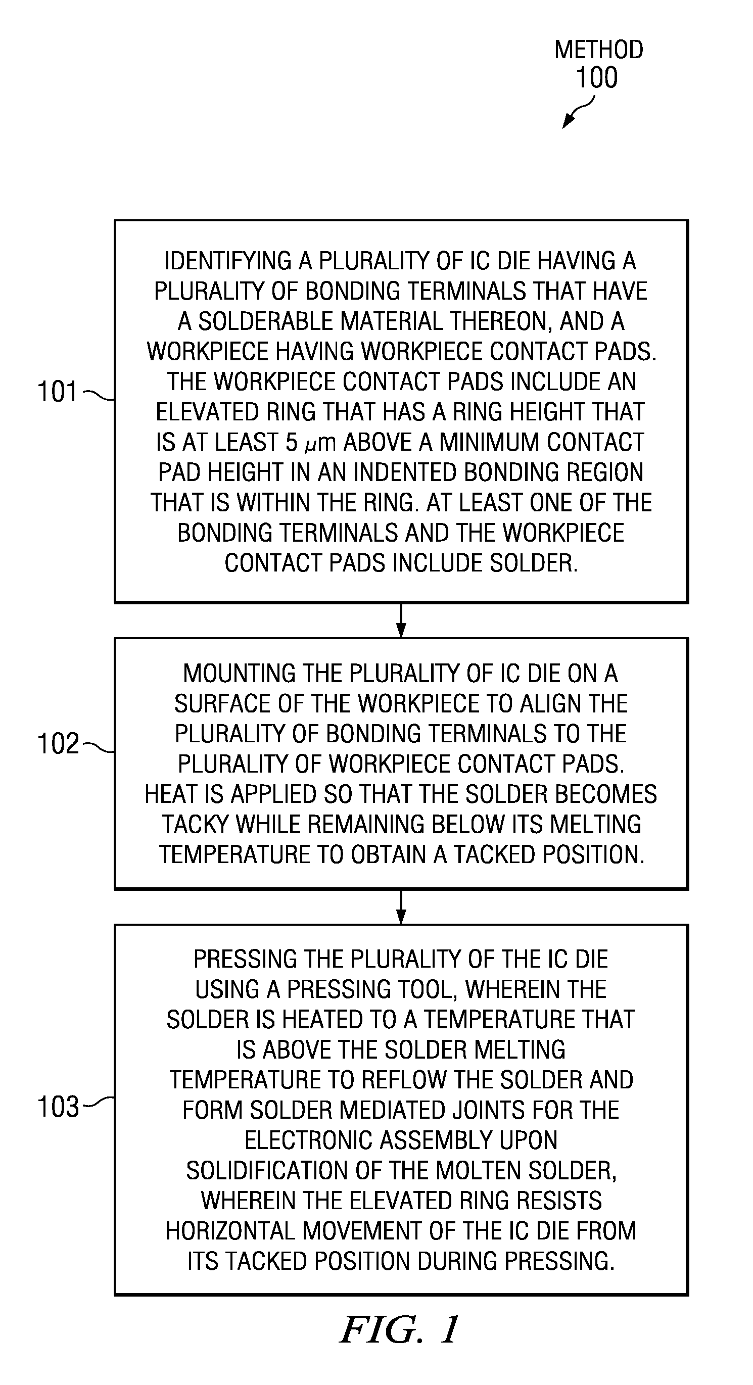
A method of forming an electronic assembly including a plurality of IC die having bonding terminals that have a solderable material thereon and a workpiece. The workpiece includes workpiece contact pads including an elevated ring having a ring height at least 5 μm above a minimum contact pad height in an indented bonding region that is within the elevated ring. The bonding terminals and/or the plurality of workpiece contact pads include solder thereon. A plurality of IC die are mounted on the workpiece. Heat is applied so that the solder becomes tacky while remaining below its melting temperature to obtain a tacked position. The plurality of IC die are pressed using a pressing tool to heat the solder to a peak temperature that is above the melting temperature. The elevated ring resists horizontal movement of the plurality of IC die from their tacked positions during pressing.

Description

CROSS REFERENCE TO RELATED APPLICATIONS[0001]This application claims the benefit of Provisional Application Ser. No. 61 / 055,674 entitled “Substrate Structure of Semiconductor Devices”, filed May 23, 2008, which is herein incorporated by reference in its entirety.FIELD OF THE INVENTION[0002]Embodiments of the present invention relate to assembly of integrated circuit (IC) comprising devices, and more particularly workpieces and to pressing-based methods for forming electronic assemblies comprising IC die joined to contact pads of workpieces with solder mediated joints.BACKGROUND[0003]In recent years, as ICs have become higher in density and the degree of integration, the electrode terminals of the ICs have rapidly become higher in pin count and narrower in pitch. To mount such an IC chip on a workpiece such as a wafer, a printed circuit board (CPB), lead frame, or other semiconductor die, flip chip mounting has been widely used for reducing wiring delay. In flip chip mounting, it is ...

Claims


Application Information

Patent Timeline
IPC IPC(8): H01L23/498H01L21/60H05K1/11
CPCH01L23/49811H01L2224/81191H01L24/16H01L24/81H01L2224/13144H01L2224/13147H01L2224/16225H01L2224/81136H01L2224/81801H01L2924/01046H01L2924/01079H01L2924/09701H01L2924/14H05K1/111H05K3/3436H05K3/3452H05K2201/09745H05K2201/099H05K2201/09909H05K2201/10674H05K2203/0369H05K2203/167H01L24/12H01L2924/00013H01L2924/00014H01L2224/13099H01L2924/00H01L2224/13023H01L2224/16237H01L2224/16245H01L2224/8114Y02P70/50
Inventor TAKAHASHI, YOSHIMIMASUMOTO, KENJI
Owner TEXAS INSTR INC
Why Eureka
Try Eureka