Coreless motor

a technology of motors and cores, applied in the direction of dynamo-electric machines, electrical equipment, supports/enclosures/casings, etc., can solve the problem of only achieving a small downsizing of motors, and achieve the effect of convenient assembly

Active Publication Date: 2009-11-26
CANON KK +1
View PDF5 Cites 10 Cited by
  • Summary
  • Abstract
  • Description
  • Claims
  • Application Information

AI Technical Summary

Benefits of technology

[0007]The present invention provides a coreless motor able to be downsized and easy to ensure the concentricity of a motor shaft, a magnet, and an outer cylinder, thereby offering a structure easy to be assembled.
[0010]According to the present invention, a coreless motor can be provided that is able to be downsized and that has a structure which is easy to be assembled and with which the concentricity between the motor shaft, the magnet, and the outer cylinder can easily be ensured.

Problems solved by technology

With the arrangement disclosed in Japanese Laid-open Patent Publication No. 8-186955, however, a downsizing of the motor can only slightly be achieved by the one-piece design of the motor and the speed-reducer mechanism.

Method used


Image

  • Coreless motor
  • Coreless motor
  • Coreless motor

Examples


embodiment

[0030]The present inventor has created a coreless motor able to be downsized and eliminate the drawbacks of the coreless motor in FIGS. 7 to 9. In the following, a description will be given of a coreless motor according to one embodiment of this invention.

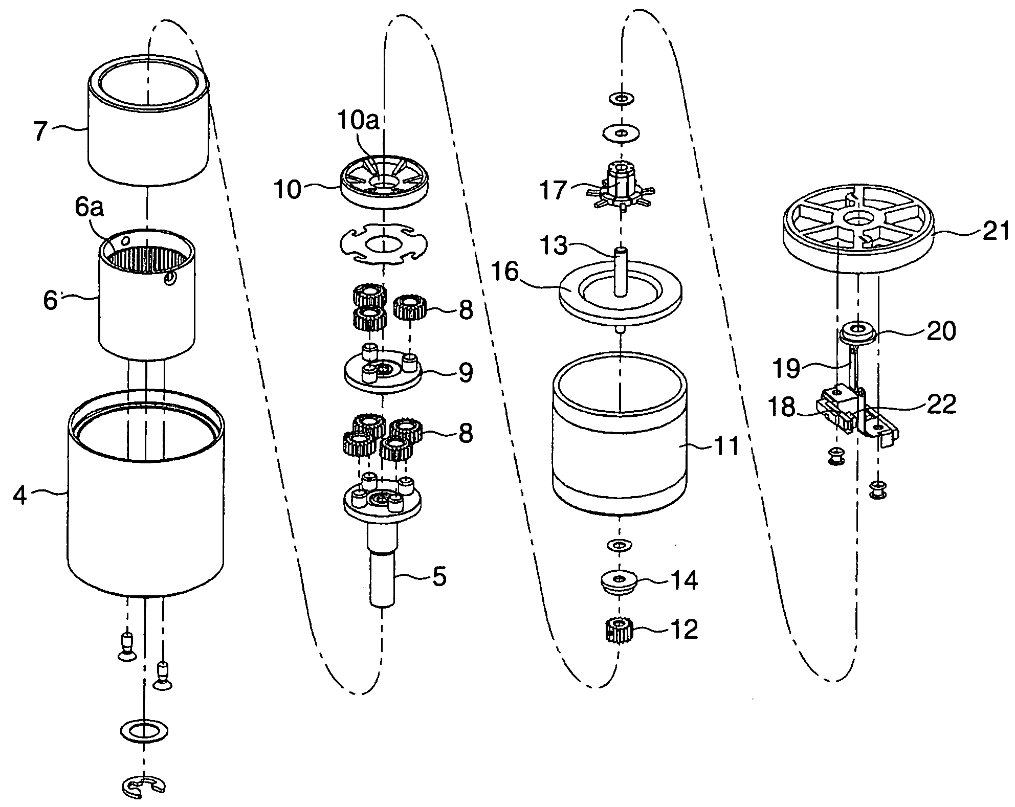
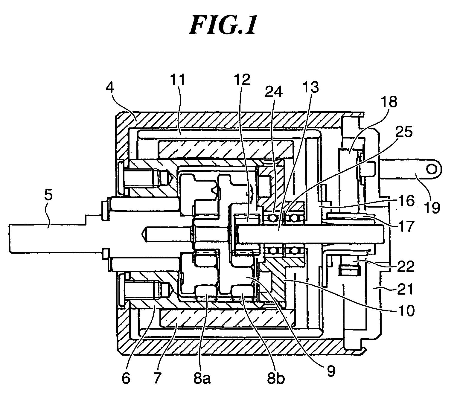
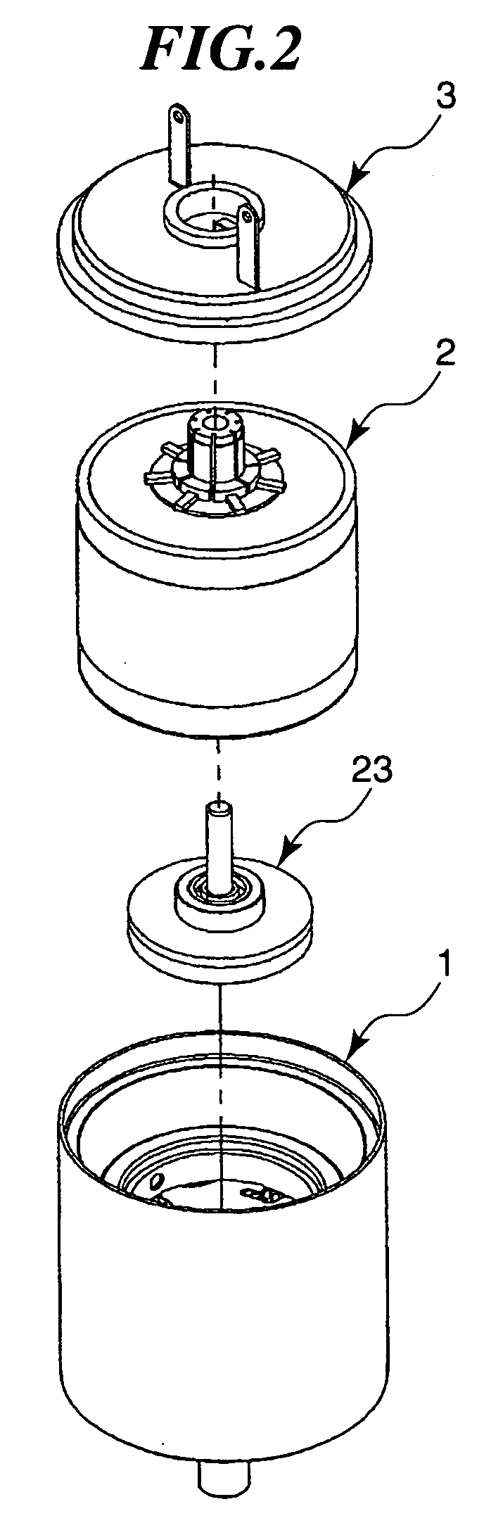
[0031]FIGS. 1 to 6 show the construction of the coreless motor according to the one embodiment of this invention. Specifically, FIG. 1 shows the construction of the coreless motor in cross section, FIG. 2 shows respective units of the coreless motor in exploded perspective view, and FIGS. 3 to 6 show in exploded perspective views the constructions of an outer cylinder gear unit, a motor shaft unit, a rotor unit, and an outer lid unit of the coreless motor. Like parts which are the same as or similar to those shown in FIGS. 7 to 9 will be denoted by like reference numerals.

[0032]As shown in FIG. 1, the coreless motor of this embodiment is configured to have a planetary gear speed reducer disposed inside a magnet 7. As shown in FIG. ...


PUM


Abstract

A coreless motor able to be downsized and easy to be assembled and to ensure the concentricity between a motor shaft, a magnet, and an outer cylinder. The coreless motor includes an outer cylinder gear unit having an output shaft and a speed-reducer mechanism incorporated into a field assembly having a magnet fitted on an inner yoke and an outer cylinder fitted on an outer periphery of the magnet, a motor shaft unit having an inner lid rotatably supporting a motor shaft via ball bearings, a rotor unit having a circular plate attached with a commutator electrically connected to a coil, an outer lid unit having an outer lid mounted with brushes. The inner lid is incorporated in the inner yoke, the coil is incorporated in between the outer cylinder and the magnet, and the outer lid unit is attached to the rotor unit and the outer cylinder.

Description

BACKGROUND OF THE INVENTION[0001]1. Field of the Invention[0002]The present invention relates to a coreless motor with speed-reducer mechanism.[0003]2. Description of the Related Art[0004]To attain a speed-reduced motor output, a speed-reducer mechanism is generally provided between a motor output shaft and a desired output shaft. The speed-reducer mechanism is disposed outside or inside the motor. Even in the case of speed-reducer mechanisms disposed inside the motor, most of them are merely disposed inside a motor housing, but disposed outside basic motor components such as an armature and a rotor (Japanese Laid-open Patent Publication No. 8-186955).[0005]The advantages of an arrangement having a motor and a gear head (speed-reducer mechanism) both incorporated in the same housing as disclosed in the just-mentioned patent publication are that intermediate component parts can be eliminated, which are required for coupling and positioning the motor and the speed-reducer mechanism wh...

Claims


Application Information

Patent Timeline
Patent Type & Authority Applications(United States)
IPC IPC(8): H02K7/116H02K23/04
CPCH02K5/145H02K23/58H02K7/116
Inventor FUKUOKA, RYUUSEI
Owner CANON KK
Why Eureka
Try Eureka