Touch-sensitive liquid crystal display device with built-in touch mechanism and method and method for driving same

a liquid crystal display and built-in touch technology, applied in the direction of instruments, computing, electric digital data processing, etc., can solve the problems of reducing the total weight of the integrated lcd device of the touch panel, affecting the overall weight of the lcd device thus obtained, and affecting the overall weight of the lcd device. , the effect of reducing the total weight of the lcd devi

Inactive Publication Date: 2009-11-26
INNOLUX CORP
View PDF10 Cites 105 Cited by
  • Summary
  • Abstract
  • Description
  • Claims
  • Application Information

AI Technical Summary

Problems solved by technology

That is, the addition of the touch panel and adhesive material to the LCD panel substantially contributes to the total weight of the touch panel integrated LCD device thus obtained.
Furthermore, the touch panel and the adhesive material possess optical characteristics which can lead to undesirable effects such as absorption, refraction and reflection.
As a result, the touch panel integrated LCD device may suffer from inferior image presentation due to factors such as lower transmittance and optical disturbance.

Method used


Image

  • Touch-sensitive liquid crystal display device with built-in touch mechanism and
method and method for driving same
  • Touch-sensitive liquid crystal display device with built-in touch mechanism and
method and method for driving same
  • Touch-sensitive liquid crystal display device with built-in touch mechanism and
method and method for driving same

Examples


first embodiment

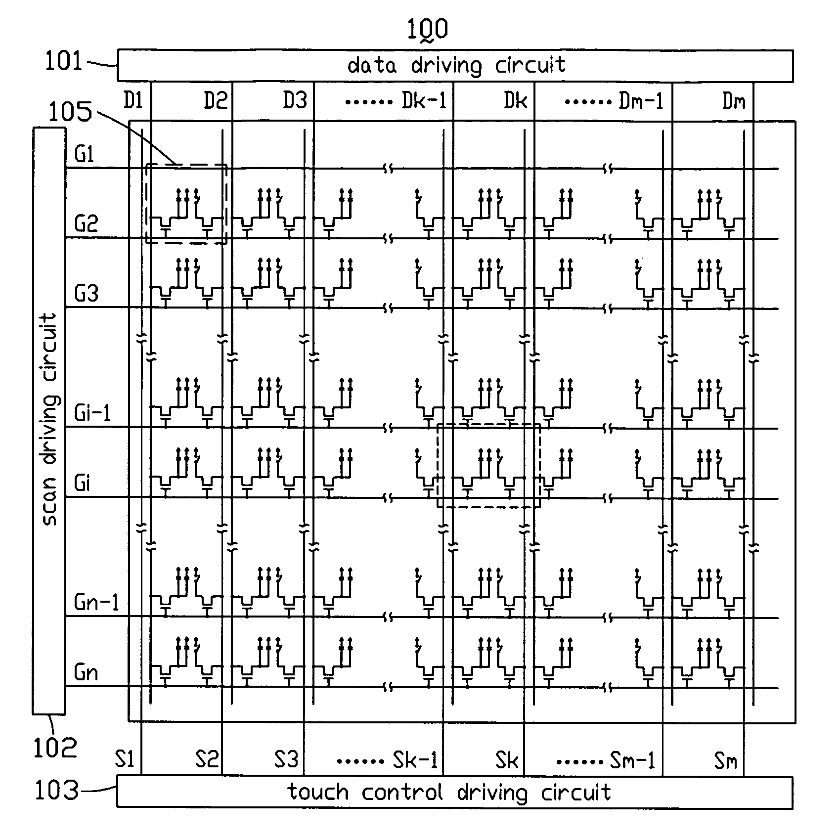
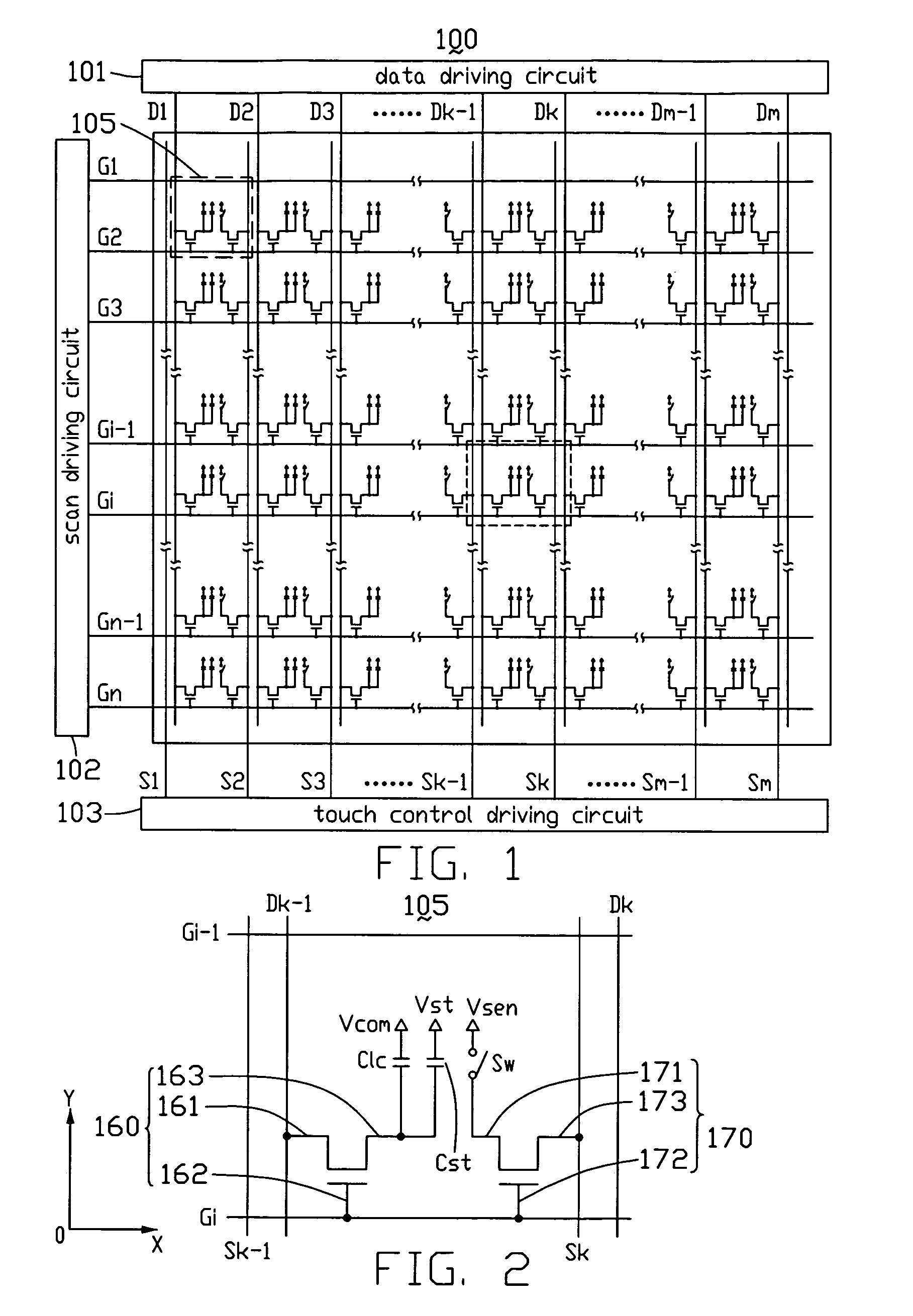
[0018]FIG. 1 is a schematic circuit diagram of a touch-sensitive LCD device provided by the present disclosure. The touch-sensitive LCD device 100 includes a data driving circuit 101 electrically connected to a plurality of data lines D1-Dm (where “m” is a nature number) for providing data signals thereto, and a scan driving circuit 102 electrically connected to a plurality of scan lines G1-Gn (where “n” is a nature number) for providing scanning signals thereto. The data lines D1-Dm are parallel to each other, with each data line D1-Dm extending along a first direction. The scan lines D1-Dm are parallel to each other, with each scan line G1-Gn extending along a second direction that is perpendicular to the first direction. Thus, a plurality of pixel units 105 are defined by the crossing data lines D1-Dm and the scan lines G1-Gn. The touch-sensitive LCD device 100 provided by the present disclosure further includes a touch control driving circuit 103 electrically connected to a plur...

second embodiment

[0037]Referring to FIGS. 7-8, FIG. 7 is an enlarged circuit diagram of one pixel unit of a touch-sensitive LCD device provided by the present disclosure, FIG. 8 is an enlarged construction of the pixel unit of FIG. 7.

[0038]The touch-sensitive LCD device 200 is similar to the touch-sensitive LCD device 100 of the first embodiment, only differs in that: in each pixel unit, a first TFT 260 is positioned at the intersection of the corresponding data line Dk−1 (where 2≦k≦m) and the corresponding scan line Gi (where 2≦i≦m), with a gate 262 electrically connected to the scan line Gi, and a second TFT 270 is positioned at the intersection of a corresponding sensing line Sk (where 2≦k≦m) and the corresponding scan line Gi−1, which is prior to the scan line Gi. Thus, the scan line Gi−1 is arranged for scan the second TFT 270, and the scan line Gi is arranged for scan the first TFT 260. Thus, the first and second TFTs 260, 270 are scanned by different scan lines Gi, Gi−1. This further eliminat...


PUM


Abstract

A touch-sensitive liquid crystal display (LCD) device includes a first substrate, a second substrate generally opposite to the first substrate, a liquid crystal layer sandwiched between the first substrate and the second substrate, a first scan line, a data line perpendicular to the first scan line, a sensing line parallel to the data line, and a first transistor formed at an inner side of the first substrate adjacent to the liquid crystal layer, and a common electrode formed at an inner side of the second substrate adjacent to the liquid crystal layer. A gate of the first transistor is electrically connected to the first gate line. A drain of the first transistor is electrically connected to sensing line. A source of the first transistor is electrically connectable to the common electrode depending on an external pressure applied on the second substrate.

Description

BACKGROUND[0001]1. Technical Field[0002]The present disclosure relates to liquid crystal display (LCD) devices, and particularly to a touch-sensitive LCD device with built-in touch mechanism and a method for driving the touch-sensitive LCD device.[0003]2. Description of Related Art[0004]The LCD device has been used as an image display means in a wide variety of applications. A touch panel for inputting signals via a display screen of an LCD device allows a user to select desired information while viewing images without depending on other separate inputting devices such as a keyboard, a mouse or a remote controller. The touch panel thus meets many demands for user-friendly, simplified and convenient operation of an LCD device.[0005]State-of-the-art types of touch panels include resistive, capacitive, acoustic, and infrared (IR) touch panels, among others. One typical touch panel has a rectangular transparent panel, and is stacked on and integrated with an LCD panel of an LCD device. ...

Claims


Application Information

Patent Timeline
Patent Type & Authority Applications(United States)
IPC IPC(8): G06F3/041
CPCG06F3/0412G06F3/047
Inventor CHEN, HSIN-LIHUNG, CHAO-YILAI, CHAO-CHIN
Owner INNOLUX CORP
Why Eureka
Try Eureka