
Method and Device for Computing Computer-Generated Video Holograms

a computer-generated video and hologram technology, applied in the field of method and device for computing computer-generated holograms, can solve the problems of high computational speed, low pixel resolution and low pixel count currently feasible with conventional slms, and the inability to meet the demands of processing speed, and achieve the effect of reducing processing speed, reducing the dimension of the observer window, and reducing the resolution

Active Publication Date: 2009-11-26
SEEREAL TECHNOLOGIES
View PDF13 Cites 49 Cited by
  • Summary
  • Abstract
  • Description
  • Claims
  • Application Information

AI Technical Summary

Benefits of technology

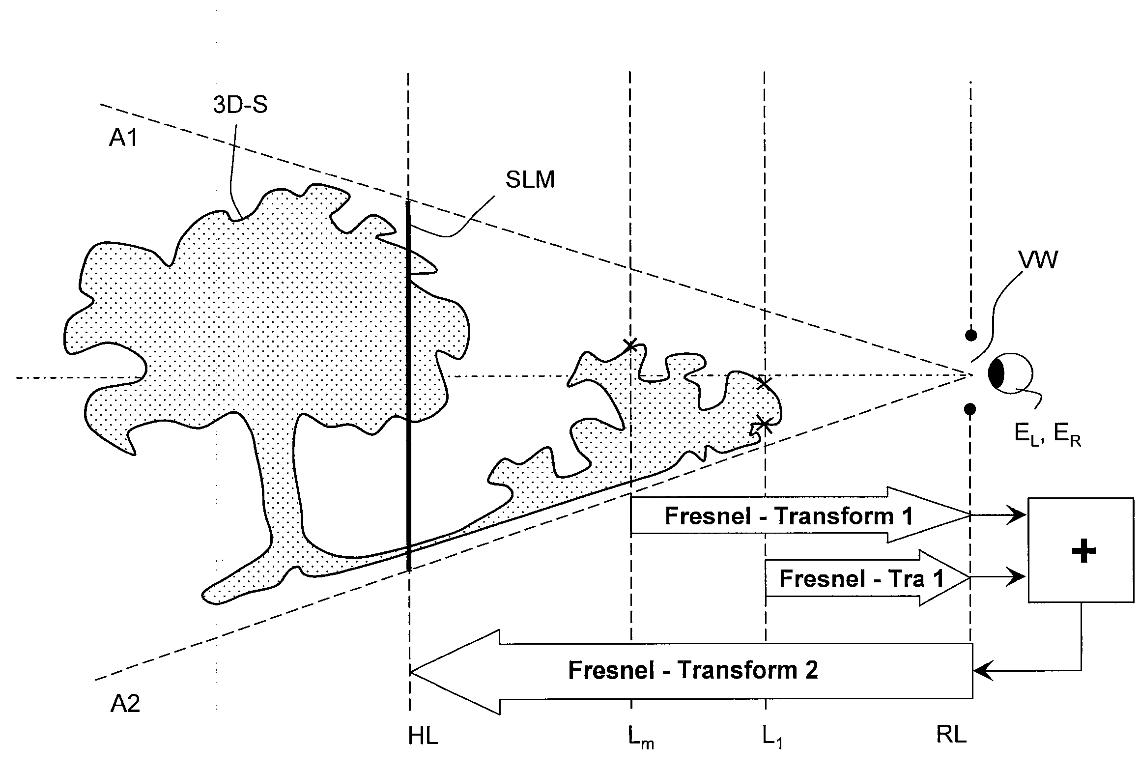
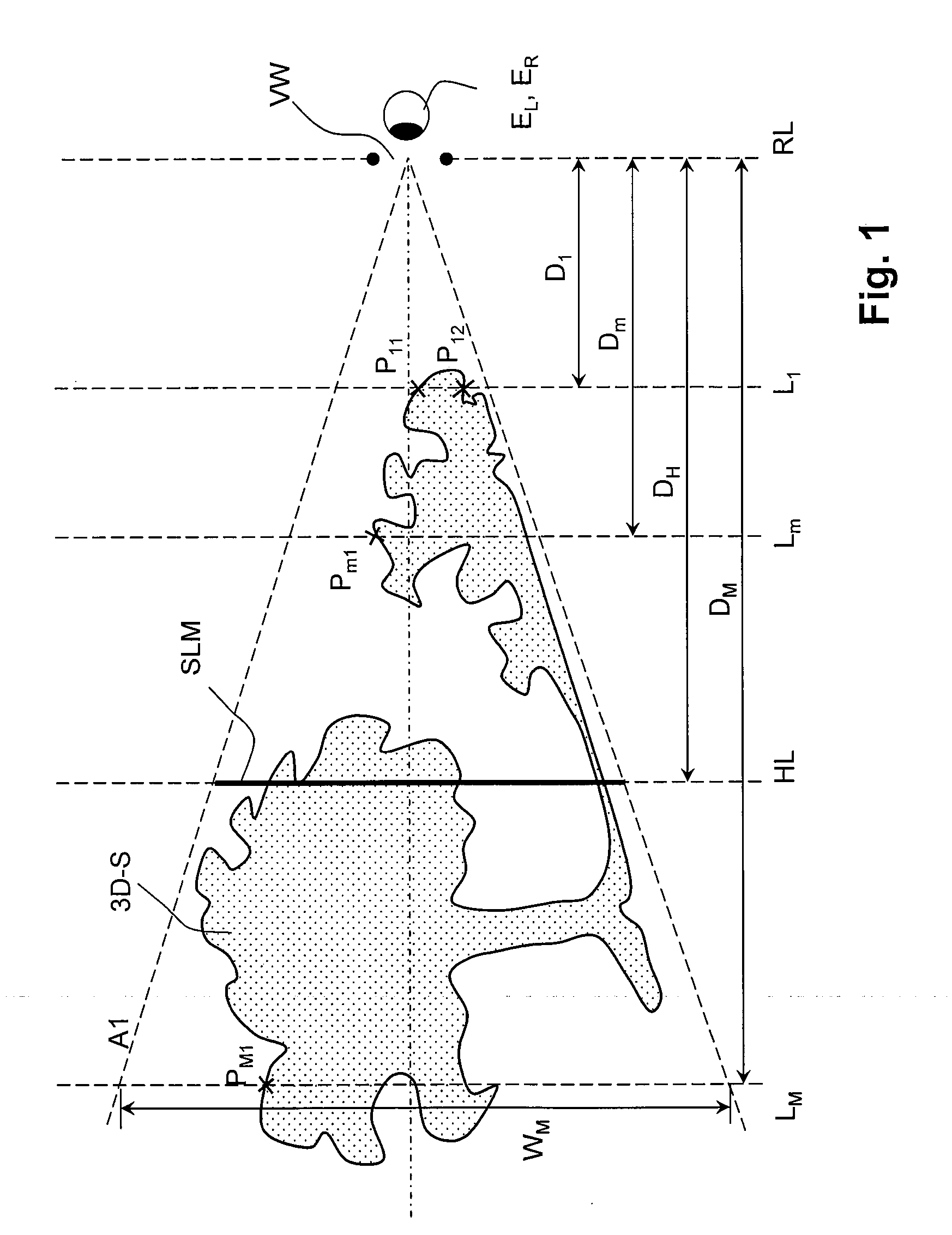
The invention provides a method for speeding up the computation of computer-generated video holograms by using a virtual section layer approach. This allows for simultaneous reconstruction of a three-dimensional scene while maintaining the spatial resolution and reconstruction quality. The method also allows for large computer-generated holograms to be generated and transferred to a video hologram display. The invention uses a diffraction formulae approach to calculate the aggregated wave field, which contains the entire optical information about the three-dimensional scene within the achieved accuracy. The method also reduces speckle noise and enhances brightness or diffraction efficiency and brightness definition in the reference layer of the scene. The invention is particularly useful in combination with video hologram display technology.

Problems solved by technology

A common problem in reconstructing three-dimensional scenes is the low pixel resolution and low pixel count currently feasible with conventional SLMs.
This requires costly hardware and high computational speed for calculating the video hologram.
Affordable real-time displays and devices with fast enough computational speed which meet these demands are currently not commercially available.
One disadvantage of the encoding technique described in this application is that it is based on a computationally intensive operations performed on every single point in the object to be reconstructed.
However, although parallel processing when computing the optimized sub-holograms increases the processing speed, the required computing power is not reduced.
A disadvantage is that real-time sequential reconstruction of each section layer requires extremely fast computing means and a light modulator matrix which is capable of reconstructing several hundreds of section holograms per second.
A satisfactory and natural real-time reconstruction of moving three-dimensional scenes using known computing and displaying means is not expected due to the low speeds and the fact that the reconstruction is restricted to the interior of the hologram display.

Method used


Image

  • Method and Device for Computing Computer-Generated Video Holograms
  • Method and Device for Computing Computer-Generated Video Holograms
  • Method and Device for Computing Computer-Generated Video Holograms

Examples


Embodiment Construction

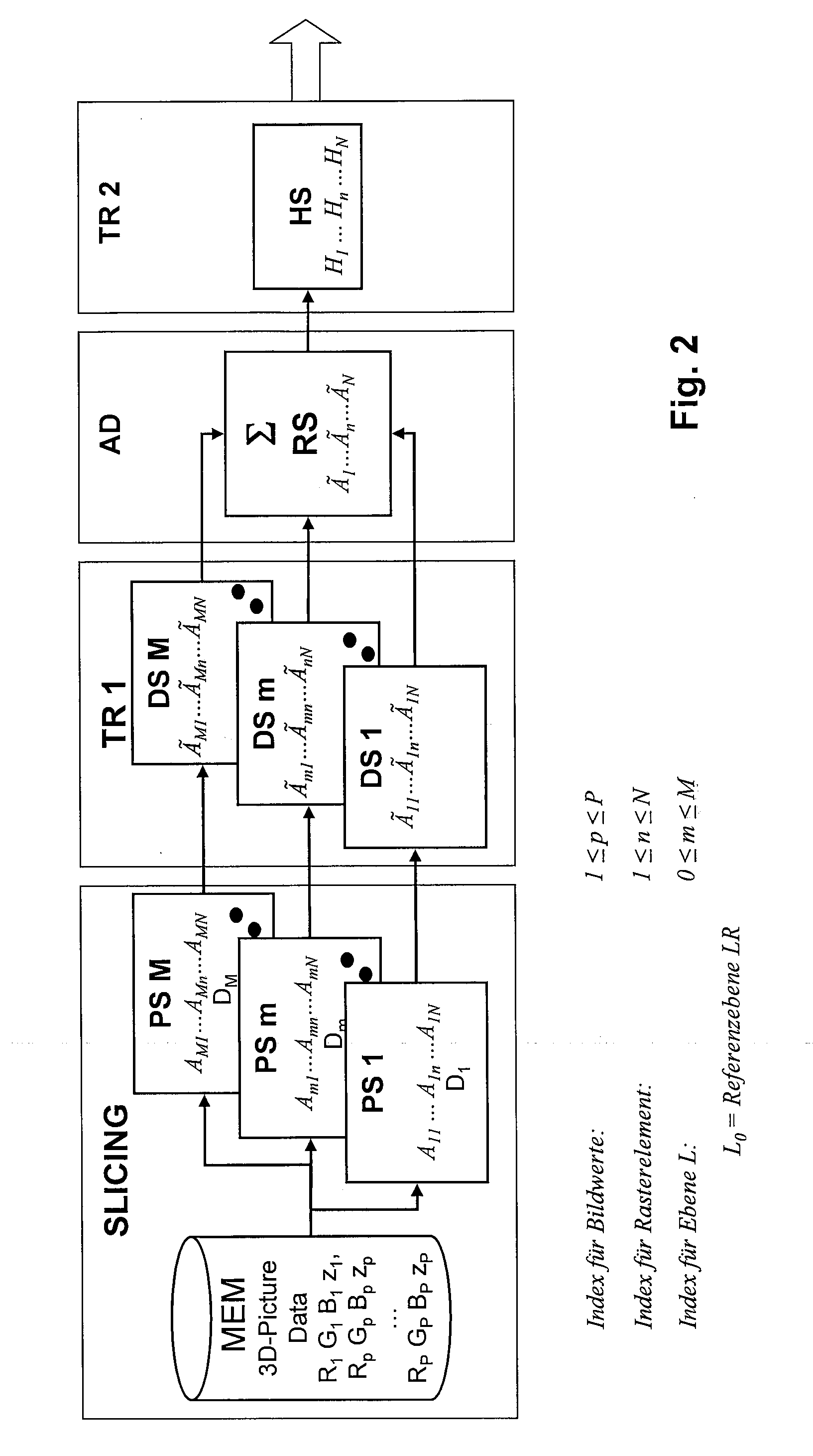
[0068]The computation of video holograms with a hologram processor is based on original object information of a real or virtual three-dimensional scene, including values for spatial distribution of the light amplitudes in an RGB or RGB-compatible format. These values are available in a known file format and can be called up from a data memory by a hologram processor. This object information contains for example, in the case of an object point file format BMP for each discrete object point of the three-dimensional scene, a set of complex color object point data Ro, Go, Bo for the respective two-dimensional coordinates. The data memory MEM also provides depth information zo of the three-dimensional scene. It is irrelevant for the depth information zo for each point whether it is already provided in the first video image file or whether it is computed by the processor from at least one second file containing additional information.

[0069]To facilitate understanding of the complex proces...


PUM


Abstract

The data defining an object to be holographically reconstructed is first arranged into a number of virtual section layers, each layer defining a two-dimensional object data sets, such that a video hologram data set can be calculated from some or all of these two-dimensional object data sets. The first step is to transform each two-dimensional object data set to a two-dimensional wave field distribution. This wave field distribution is calculated for a virtual observer window in a reference layer at a finite distance from the video hologram layer. Next, the calculated two-dimensional wave field distributions for the virtual observer window, for all two-dimensional object data sets of section layers, are added to define an aggregated observer window data set. Then, the aggregated observer window data set is transformed from the reference layer to the video hologram layer, to generate the video hologram data set for the computer-generated video hologram.

Description

CROSS-REFERENCE TO RELATED APPLICATIONS[0001]This application is a divisional of co-pending U.S. application Ser. No. 11 / 313,977, filed Dec. 21, 2005, which claims priority to German Application No. DE 10 2004 063838, filed on Dec. 23, 2004, the entire contents of which are hereby incorporated in total by reference.BACKGROUND OF THE INVENTION[0002]1. Field of the Invention[0003]The present invention relates to a method and device for computing computer-generated holograms (CGH), especially real-time or near real-time holograms, e.g. video holograms, which are made up of individually controllable hologram cells; each cell displays complex-valued data. Besides stills, real-time video holograms are of particular interest. Electro-holography aims at a realization of CGH in real-time. The electro-hologram display is effectively a Spatial Light Modulator (SLM) with controllable pixels reconstructing object points by spatial modulating an illuminating light. Throughout this specification, ...

Claims


Application Information

Patent Timeline
Patent Type & Authority Applications(United States)
IPC IPC(8): G03H1/08
CPCG03H1/22G03H2001/269G03H2001/0816G03H2001/0858G03H2001/2236G03H2001/2242G03H2001/2263G03H2001/2271G03H2001/303G03H2210/33G03H2210/454G03H2222/34G03H2223/16G03H2225/35G03H2226/02G03H2226/05G03H1/0808G03H2210/30G03H1/0005G03H1/268G03H1/32G03H2001/0088G03H1/2294G03H1/04
Inventor SCHWERDTNER, ARMIN
Owner SEEREAL TECHNOLOGIES
Learn More