Supercharge Your Innovation With Domain-Expert AI Agents!

Battery with enhanced safety

a technology of enhanced safety and batteries, applied in the direction of batteries, sustainable manufacturing/processing, wound/folded electrode electrodes, etc., can solve the problems of unidentical capacity, impedance, discharge and charge rate, over-charge or over-charge, etc., and achieve the effect of improving safety

Inactive Publication Date: 2009-11-26
BOSTON POWER INC
View PDF31 Cites 35 Cited by
  • Summary
  • Abstract
  • Description
  • Claims
  • Application Information

AI Technical Summary

Benefits of technology

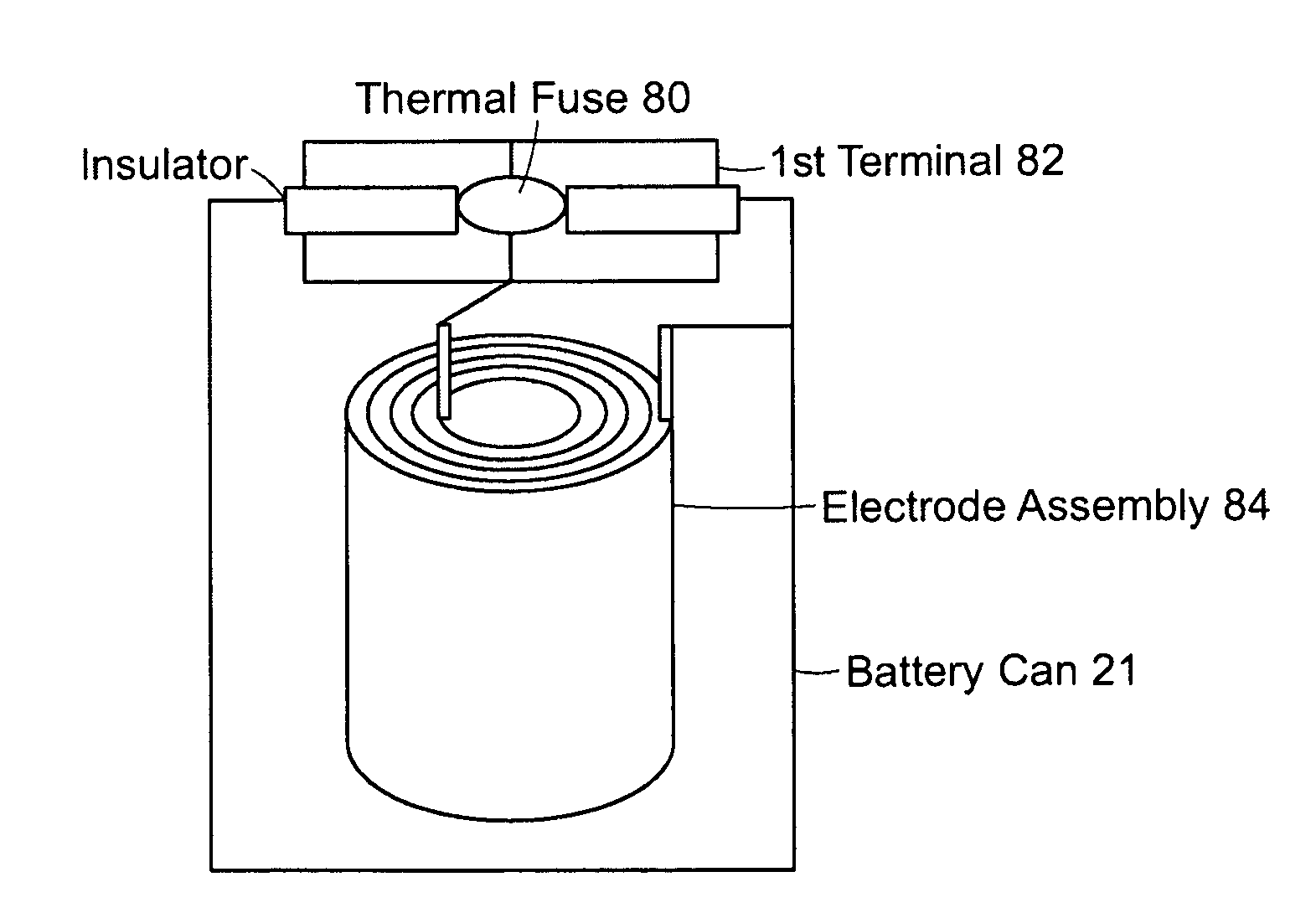
"The present invention is directed to a battery that includes a current interrupt device (CID) to prevent potential electrochemical communication between the first and second terminals when the CID is activated. The battery also includes insulation to interrupt potential electrochemical communication between the first and second terminals when the CID is activated. This prevents the flow of current through the cell and avoids the decomposition of electrolytes, which can lead to an increase in internal cell pressure and potential cell explosion. The technical effect of this invention is to improve the safety and reliability of lithium-ion batteries."

Problems solved by technology

However, when cells are aged and cycled, they tend to deviate from the initial ideal conditions, resulting in an unbalanced cell pack (e.g., unidentical capacity, impedance, discharge and charge rate).
This unbalance among the cells may cause over-charge or over-discharge during normal operation of the rechargeable batteries, and in turn can impose safety concerns, such as explosion (i.e., rapid gas release and possibility for fire).
Although there have been a various types of safety measures have been designed and employed, unfortunate accidents associated with batteries, such as explosion, have been reported in the art.

Method used


Image

  • Battery with enhanced safety
  • Battery with enhanced safety
  • Battery with enhanced safety

Examples


Embodiment Construction

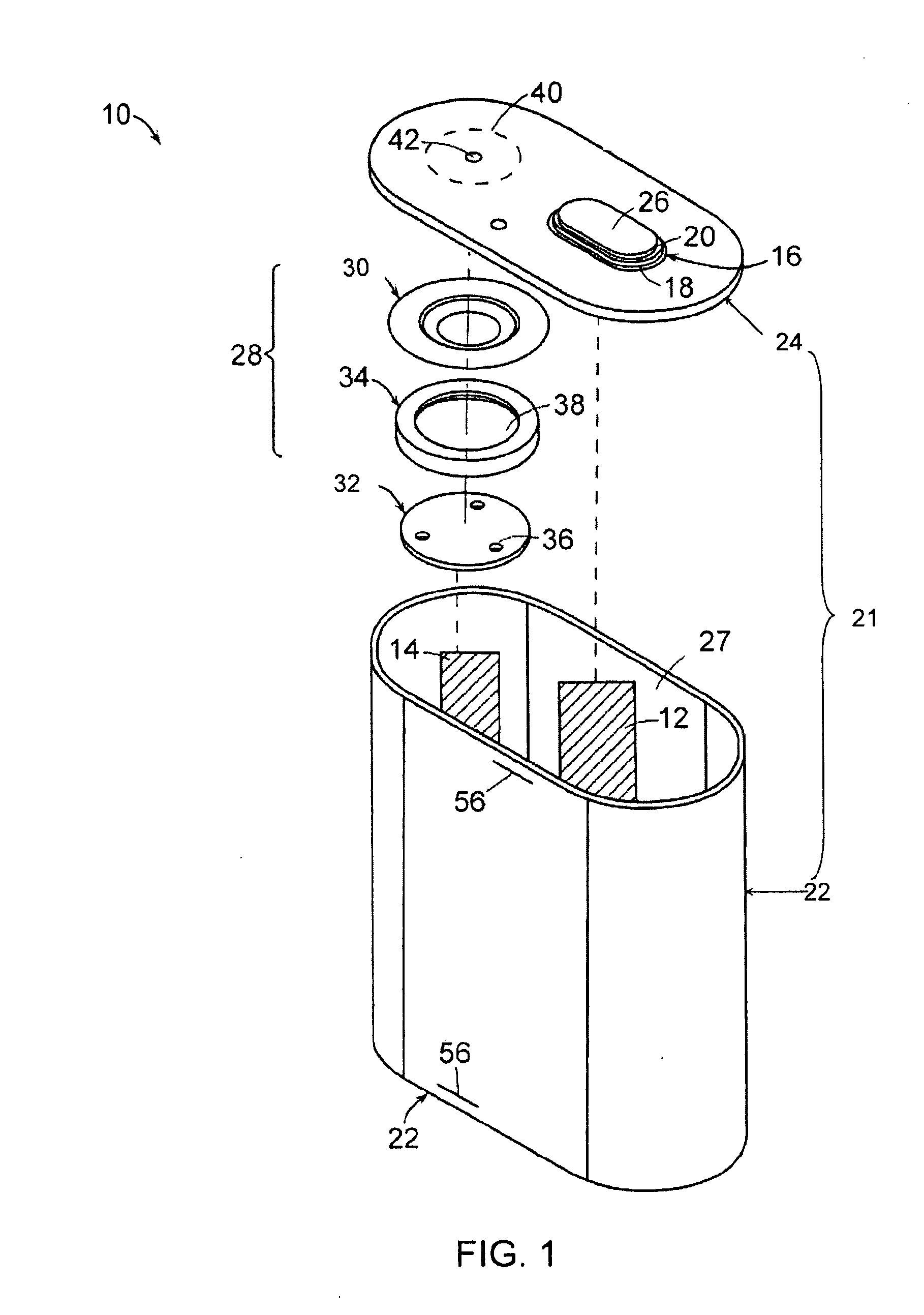
[0023]The foregoing will be apparent from the following more particular description of example embodiments of the invention, as illustrated in the accompanying drawings in which like reference characters refer to the same parts throughout the different views. The drawings are not necessarily to scale, emphasis instead being placed upon illustrating embodiments of the present invention.

[0024]As used herein, the “terminals” of the batteries of the invention mean the parts or surfaces of the batteries to which external electric circuits are connected.

[0025]The batteries of the invention typically include a first terminal in electrical communication with a first electrode, and a second terminal in electrical communication with a second electrode. The first and second electrodes are contained within a cell casing, for example, in a “jelly roll” form. The first terminal can be either a positive terminal in electrical communication with a positive electrode of the battery, or a negative te...


PUM

PropertyMeasurementUnit
thicknessaaaaaaaaaa
thicknessaaaaaaaaaa
thicknessaaaaaaaaaa

Abstract

A battery includes a cell casing; a first terminal; a second terminal in electrical communication with the cell casing and electrically insulated from the first terminal; an electrode assembly in the cell casing; a current interrupt device (CID) in electrical communication with the first terminal and the first electrode or with the second terminal and the second electrode; and insulation that interrupts potential electrochemical communication between the first electrode and the second terminal or between the second electrode and the first terminal. The electrode assembly includes a first electrode in electrical communication with the first terminal, a second electrode in electrical communication with the second terminal, and an electrolyte between the first and second electrodes. The insulation interrupts potential electrochemical communication between the first electrode and the second terminal or between the second electrode and the first terminal when under a charging or overcharging condition and when the CID is activated, thereby interrupting the electrical communication between the first terminal and the first electrode or between the second terminal and the second electrode.

Description

RELATED APPLICATION[0001]This application claims the benefit of U.S. Provisional Application No. 61 / 125,327, filed on Apr. 24, 2008. The entire teachings of the above application are incorporated herein by reference.BACKGROUND OF THE INVENTION[0002]Rechargeable batteries, such as lithium-ion rechargeable batteries, are widely used as electrical power for battery-powered portable electronic devices, such as cellular telephones, portable computers, camcorders, digital cameras, PDAs and the like. A typical lithium-ion battery pack for such portable electronic devices employs multiple cells that are configured in parallel and in series. For example, a lithium-ion battery pack may include several blocks connected in series where each block includes one or more cells connected in parallel. Each block typically has an electronic control that monitors voltage levels of the block. In an ideal configuration, each of the cells included in the battery pack is identical. However, when cells are ...

Claims


Application Information

Patent Timeline
Patent Type & Authority Applications(United States)
IPC IPC(8): H02H7/18H01M4/82H02J7/00H01M50/119H01M50/583H01M50/588H01M50/595
CPCH01M2/0275H01M2/0292H01M2/12H01M2/1235H01M2/1673H01M2/34Y10T29/49108H01M10/0587H01M2200/00H01M2200/103H01M2200/20H01M2/0287H01M10/0431Y02E60/10H01M50/124H01M50/1245H01M50/342H01M50/30H01M50/46Y02P70/50H01M50/588H01M50/595H01M50/583H01M50/119H01M50/578H01M50/581H01M50/155H01M50/20
Inventor ONNERUD, PERSONG, YANNINGCHAMBERLAIN, II, RICHARD V.
Owner BOSTON POWER INC
Features
  • R&D
  • Intellectual Property
  • Life Sciences
  • Materials
  • Tech Scout
  • Unparalleled Data Quality
  • Higher Quality Content
  • 60% Fewer Hallucinations
Learn More