Carbon Foam Based Three-Dimensional Batteries and Methods

Inactive Publication Date: 2009-11-26
PHYSICAL SCI
View PDF22 Cites 55 Cited by
  • Summary
  • Abstract
  • Description
  • Claims
  • Application Information

AI Technical Summary

Benefits of technology

[0006]The invention, in one embodiment, features a battery including a three-dimensional foam base. The three dimensional battery includes an interpenetrating network of anode and cathode separated by an electrolyti

Problems solved by technology

As electrodes are made thinner for improved power, more separator and current collector area are required, resulting in a decrease in energy

Method used


Image

  • Carbon Foam Based Three-Dimensional Batteries and Methods
  • Carbon Foam Based Three-Dimensional Batteries and Methods
  • Carbon Foam Based Three-Dimensional Batteries and Methods

Examples


Embodiment Construction

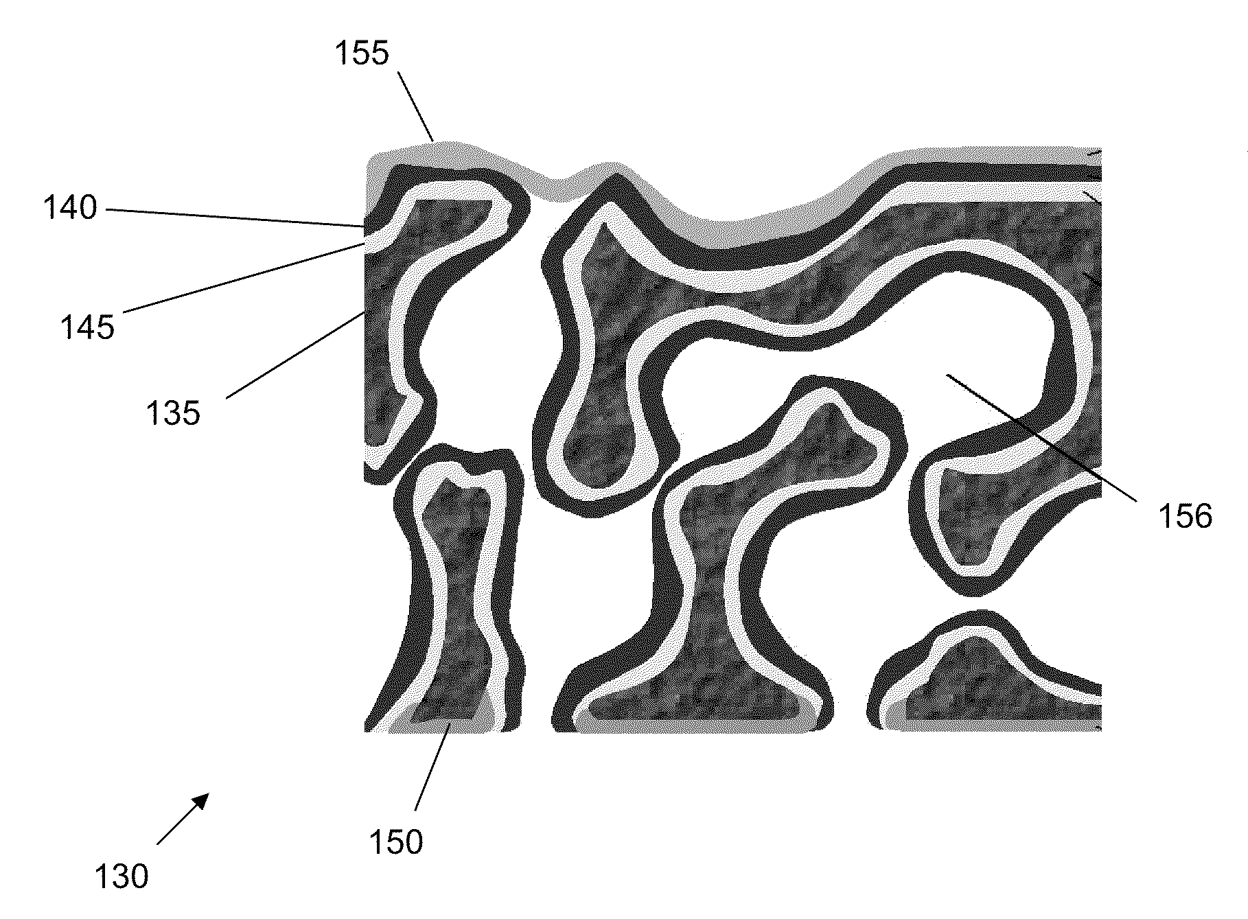
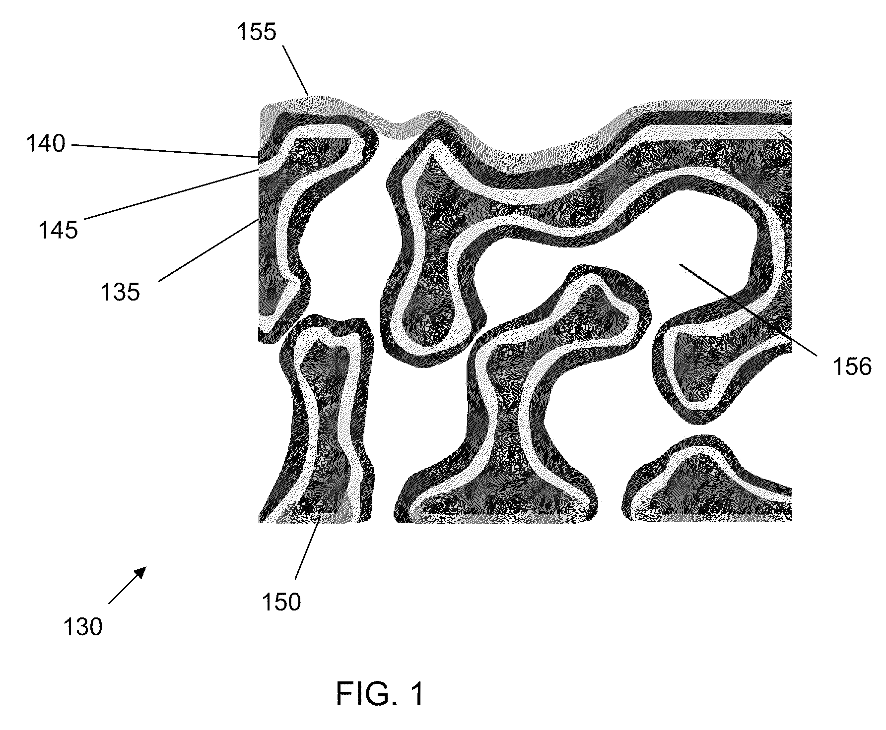
[0039]FIG. 1 is a schematic of a carbon foam based three-dimensional battery cell 130, according to an illustrative embodiment of the invention. The three dimensional battery cell 130 includes an anode 135 (e.g., negative electrode), a cathode 140 (e.g., positive electrode), a separator layer 145, an anode current collector 150 (e.g., negative current collector), and a cathode current collector 155 (e.g., positive electrode current collector). Ions are transported between the anode 135 and cathode 140 through the separator layer 145. The anode 135 can include a carbon foam base having pores 156 that allow a separator layer 145 and cathode layer 140 to infiltrate and form on the surface of the anode 135. As a result, the pores 156 allow for a greater surface area as compared to two dimensional batteries. As a result, the pores 156 allow for the anode 135, cathode 140 and separator layer 145 to be formed within a smaller volume. Two orders of magnitude higher interfacial area provides...


PUM

PropertyMeasurementUnit
Timeaaaaaaaaaa
Pore sizeaaaaaaaaaa
Pore sizeaaaaaaaaaa

Abstract

A three-dimensional battery can include a three-dimensional porous carbon foam base and an anode current collector bonded to and in electrical communication with a first region of the base. The three-dimensional battery can also include an electrolyte layer disposed over the three-dimensional porous carbon foam base and a cathode current collector bonded to and in electrical communication with a second region of the three-dimensional porous carbon foam base.

Description

CROSS-REFERENCE TO RELATED APPLICATION[0001]This application claims the benefit of and priority to U.S. Provisional Patent Application No. 60 / 956,608 filed on Aug. 17, 2007, which is owned by the assignee of the instant application and the disclosure of which is incorporated herein by reference in its entirety.STATEMENT OF GOVERNMENT INTEREST[0002]The subject matter described herein was developed in connection with funding provided by the Office of Naval Research, Prime Contract ID N00014-06-C-0192. The federal government may have rights in the technology.FIELD OF THE INVENTION[0003]The invention generally relates to a three-dimensional battery. Specifically, the invention relates to carbon foam based three-dimensional batteries and methods of making carbon foam based three-dimensional batteries.BACKGROUND OF THE INVENTION[0004]Lithium ion batteries are based on shuttling lithium ions between the negative and positive electrode insertion materials. The conventional electrode arrange...

Claims


Application Information

Patent Timeline
IPC IPC(8): H01M4/29
CPCH01M4/29H01M4/525Y02E60/124H01M10/0525Y02E60/122H01M4/587Y02E60/10
Inventor NEWMAN, ARONWHITE, KEVINHORN, QUINNLANG, CHRISTOPHER
Owner PHYSICAL SCI
Why Eureka
Try Eureka