Apparatus and method for marking an irradiation field on the surface of a patient's body

a technology of irradiation field and apparatus, which is applied in the field of apparatus and method for marking an irradiation field, can solve the problems of occupying complicated accuracy and reproducibility positioning, and taking place, so as to save valuable time in the tomography room

Inactive Publication Date: 2009-11-26
LAP LASER APPLIKATIONEN
View PDF5 Cites 11 Cited by
  • Summary
  • Abstract
  • Description
  • Claims
  • Application Information

AI Technical Summary

Benefits of technology

[0031]The apparatus of the present invention can be arranged in another room than a tomography apparatus used for determining the virtual 3D-model of the patient's body. Through this, valuable time in the tomography room is saved. The same positioning and f

Problems solved by technology

Because in this it is dealt with living human beings with soft body structures and not with rigid bodies, an accurate and reproducible positioning is complicated with very strongly ill and adipose patients in particular.
In the procedure k

Method used


Image

  • Apparatus and method for marking an irradiation field on the surface of a patient's body
  • Apparatus and method for marking an irradiation field on the surface of a patient's body
  • Apparatus and method for marking an irradiation field on the surface of a patient's body

Examples


Embodiment Construction

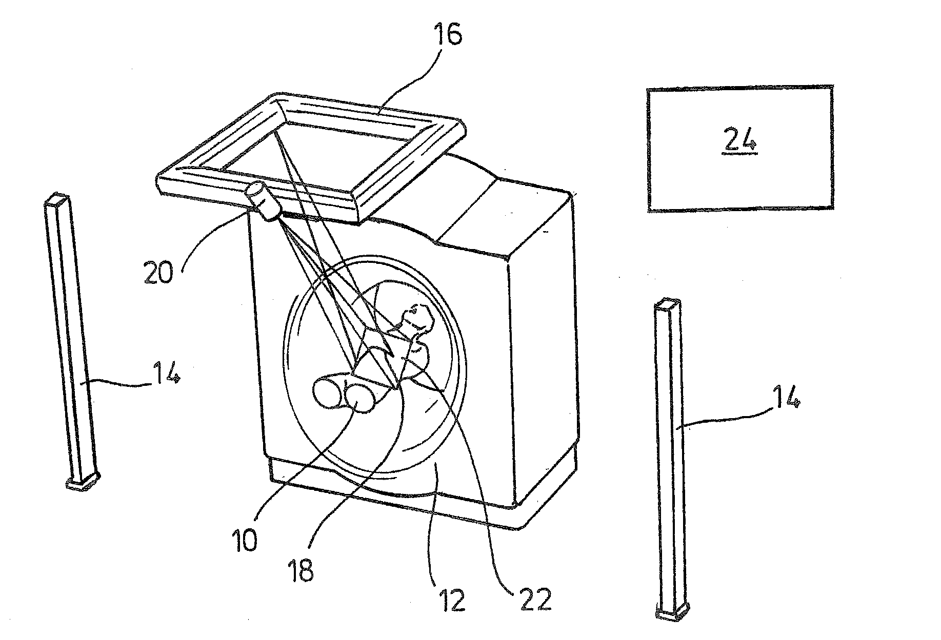
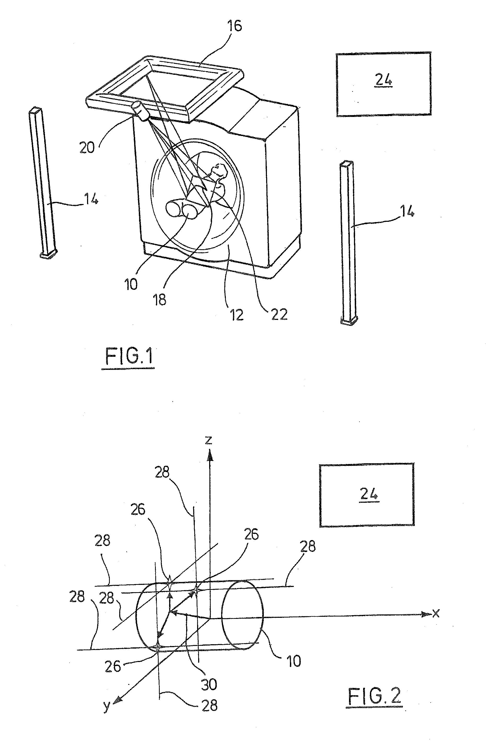
[0038]While this invention may be embodied in many different forms, there are described in detail herein a specific preferred embodiment of the invention. This description is an exemplification of the principles of the invention and is not intended to limit the invention to the particular embodiment illustrated As far as not indicated otherwise, same reference signs designate same objects in the figures. In FIG. 1, an apparatus for marking an irradiation field on the surface of a patient's body 10 represented only schematically is shown. In the realisation example in FIG. 1. the apparatus is arranged in the same room as a tomography apparatus 12 (a CT apparatus for instance) by which a virtual 3D-model of the patient's body 10 is produced for the irradiation planning. The apparatus in FIG. 1 comprises a laser system with five lasers altogether, which can be moved by motor. In this, two lasers 14 adjustable in height are provided laterally at the right and at the left side of a posit...


PUM


Abstract

The present invention is related to an apparatus for marking an irradiation field on the surface of the patient's body, which was produced by means of a virtual 3D model of a patient's body, with a laser system for determining the coordinates of at least two reference points on the surface of the patient's body in a local coordinate system assigned to the apparatus, with an analysing and control unit which is realised to determine a transformation matrix for the transformation of arbitrary coordinates from the virtual coordinate system into the local coordinate system from the coordinates of the reference points in the local coordinate system and from coordinates of the reference points in a virtual coordinate system of the virtual 3D model of the patient's body, and wherein the analysing and control unit is further realised to transform coordinates from the virtual coordinate system into the local coordinate system with the transformation matrix, and to provide the transformed coordinates to the laser system. In addition, the present invention is also related to a corresponding method.

Description

CROSS-REFERENCE TO RELATED APPLICATIONS[0001]Not applicable.STATEMENT REGARDING FEDERALLY SPONSORED RESEARCH[0002]Not applicable.BACKGROUND OF THE INVENTION[0003]The present invention is related to an apparatus and a method for marking an irradiation field, which was produced by means of a virtual 3D model of a patient's body, on the surface of the patient's body. Such irradiation fields represent desired intersection fields of a therapeutic beam, mostly of ionizing radiation and used for cancer treatment in particular, with the surface of a patient's body. In this, usually plural rays are directed to the body to be treated from different directions, so that they intersect in an isocentre. Here acts the summed-up radiation dose, and the adverse effect to the surrounding tissue is minimised. As the first step of a radiation therapy, a tomography mapping, computer tomography (CT) for instance, is established of a body region of interest of the patient which is positioned and fixed on ...

Claims


Application Information

Patent Timeline
IPC IPC(8): A61B5/05
CPCA61N5/1049A61N2005/1056A61N2005/105
Inventor KINDLEIN, JOHANNTHURN, TIM
Owner LAP LASER APPLIKATIONEN
Why Eureka
Try Eureka