Conical diffuser tip

a diffuser tip and conical technology, applied in the direction of the catheter, etc., can solve the problem of reducing the likelihood of displacing the catheter, and achieve the effect of facilitating and improving the efficiency of infusion procedures

Active Publication Date: 2009-11-26
BECTON DICKINSON & CO
View PDF23 Cites 13 Cited by
  • Summary
  • Abstract
  • Description
  • Claims
  • Application Information

AI Technical Summary

Benefits of technology

[0009]The systems and methods of the present disclosure have been developed in response to problems and needs in the art that have not yet been fully resolved

Problems solved by technology

This reduces the likelihood of displacing the c

Method used


Image

  • Conical diffuser tip
  • Conical diffuser tip
  • Conical diffuser tip

Examples


Embodiment Construction

[0027]The presently preferred embodiments of the present invention will be best understood by reference to the drawings, wherein like reference numbers indicate identical or functionally similar elements. It will be readily understood that the components of the present invention, as generally described and illustrated in the figures herein, could be arranged and designed in a wide variety of different configurations. Thus, the following more detailed description, as represented in the figures, is not intended to limit the scope of the invention as claimed, but is merely representative of presently preferred embodiments of the invention.

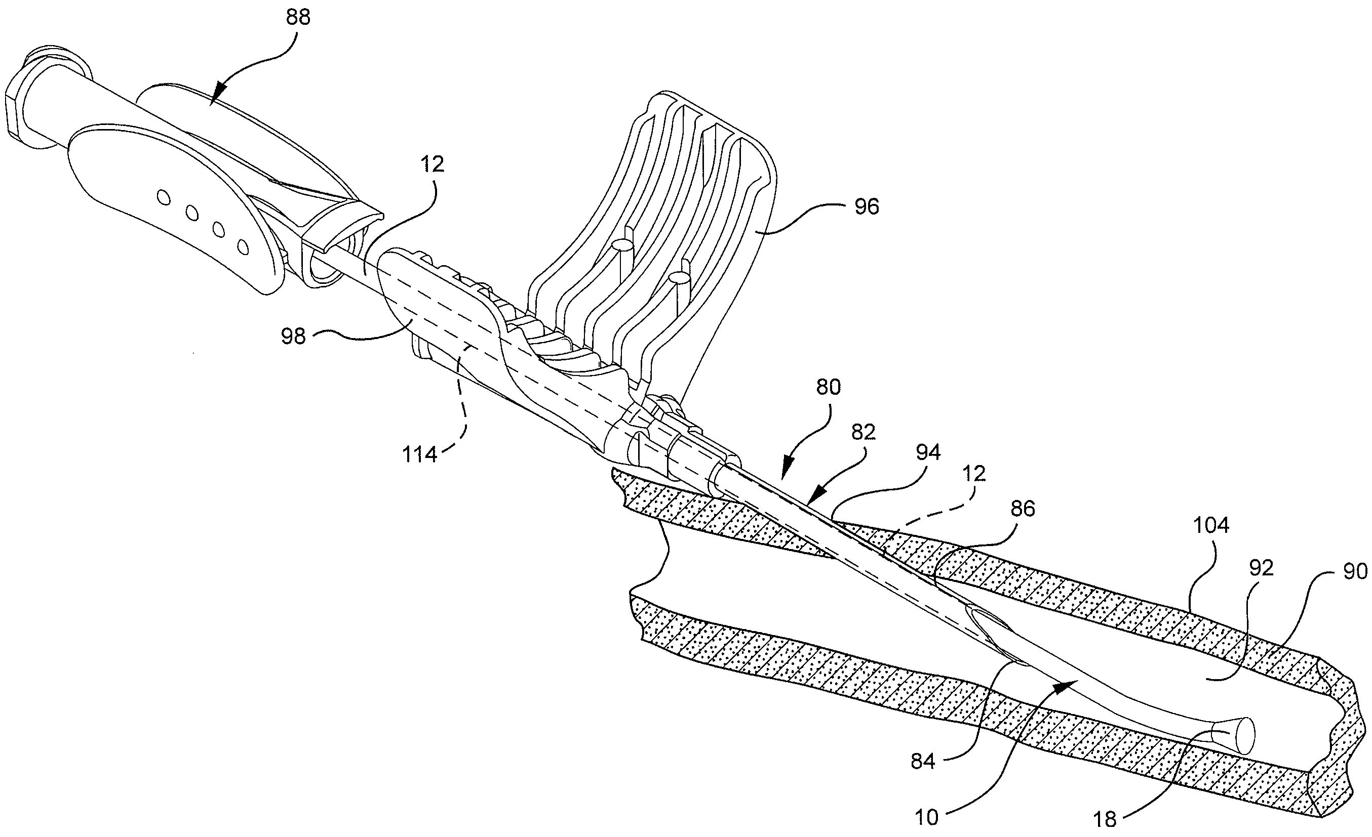
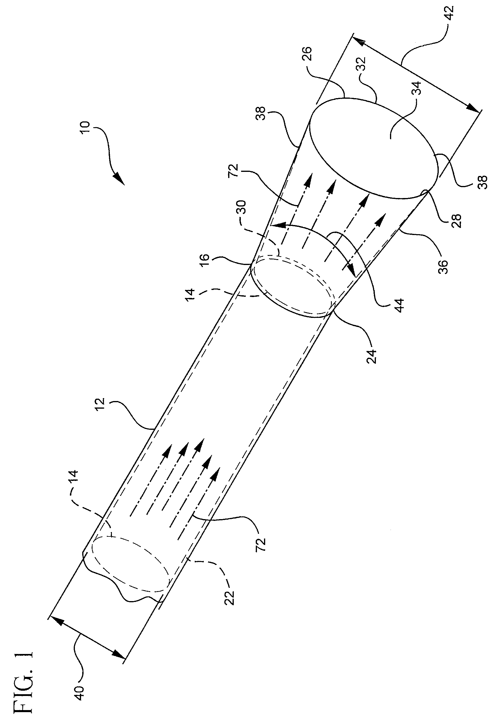
[0028]Referring now to FIG. 1, a section of a catheter 10 is illustrated. The catheter 10 comprises a catheter tube 12 and a catheter tip 18. The catheter tube 12 may comprise any length where the length is selected based on the intended application of the catheter 10. For example, the catheter 10 length may vary from a few centimeters for peripheral ...


PUM


Abstract

A catheter assembly is provided having a conical diffuser tip for use in rapid infusion procedures. The conical diffuser tip provides a flared opening whereby the velocity of an infusant is decreased as the infusant travels through the catheter tip and exits into the vascular system of a patient. This decrease in velocity proportionately reduces the backpressure and/or recoil force of the catheter assembly thereby permitting the use of higher infusion rates. The catheter tip is introduced into the vasculature of a patient via a splittable introducer needle.

Description

BACKGROUND OF THE INVENTION[0001]The present disclosure relates generally to vascular access devices and methods, including catheter assemblies and devices used with catheter assemblies. Generally, vascular access devices are used for communicating fluid with the vascular system of patients. For example, catheters are used for infusing fluid, such as saline solution, various medicaments, and / or total parenteral nutrition, into a patient, withdrawing blood from a patient, and / or monitoring various parameters of the patient's vascular system.[0002]A variety of clinical circumstances, including massive trauma, major surgical procedures, massive burns, and certain disease states, such as pancreatitis and diabetic ketoacidosis, can produce profound circulatory volume depletion. This depletion can be caused either from actual blood loss or from internal fluid imbalance. In these clinical settings, it is frequently necessary to infuse blood and / or other fluid rapidly into a patient to aver...

Claims


Application Information

Patent Timeline
IPC IPC(8): A61M25/00
CPCA61M25/0068A61M25/0069A61M25/065A61M2025/0073A61M25/0668
Inventor MCKINNON, AUSTIN JASON
Owner BECTON DICKINSON & CO
Why Eureka
Try Eureka