Method and device to fill receiving containers

a technology of receiving container and receiving container, which is applied in the direction of liquid handling, packaged goods type, instruments, etc., can solve the problems of inaccuracy, delayed flow of bingham substance at the beginning of the flow process, and complex rheological properties in particular, so as to achieve a m-over-m effect of mass flow

Inactive Publication Date: 2009-12-03
METTLER TOLEDO GMBH
View PDF4 Cites 10 Cited by
  • Summary
  • Abstract
  • Description
  • Claims
  • Application Information

AI Technical Summary

Benefits of technology

[0014]The disclosed method and device further prove to be advantageous in dispensing doses of toxic substances, as it offers the possibility to automate the dispensing process. This reduces the risk that the person attending to the process could come into contact with the toxic substance.
[0037]The rotary movement as well as the tapping has the beneficial effect that a clogging of the valve and / or the formation of powder bridges can thereby be counteracted. In this way, the ability of the powder to low freely can be preserved or enhanced.

Problems solved by technology

The delivery flow velocity u in particular is subject to many influence factors such as for example the aperture area A of the valve, the static pressure resulting from the fill level height h of the substance in the reservoir, and the rheological properties of the substance such as for example the powder grain size d. The rheological properties in particular are often very complex and subject to influence factors that are known only with limited accuracy.
For example, the delayed flow which occurs in a Bingham substance at the beginning of the flow process is difficult to take into account.
Inaccuracies occur in this case because a certain amount of time is needed for the closing of the valve and also because there is material in free fall between the valve and the receiving container during the filling process.
A problem which presents itself here is the abrupt closing of the valve.
Otherwise, there could be an undesirable change in the substance properties, i.e. the substance could get damaged.
The abrupt closing could also lead to a compaction of the material.
This compaction can change the material properties and thus the flow properties of the material, which would negatively affect the reproducibility of the filling process.
A further problem lies in the fact that in the first fill cycle, there are no data available from preceding fill cycles.
Accordingly, it is impossible to perform a correction for the first fill cycle, which may cause an error in the resultant fill quantity.
If the valve were opened and closed several times, the substance and in particular the grains of a powder to be dispensed would be exposed to shear forces which could lead to an undesirable change of the physical properties and could thus cause damage to the substance.
However, this kind of direct proportionality cannot normally be achieved in real situations, because the material properties such as for example grain size, delay in the start-up of the flow process or similar factors also work against a direct proportionality.

Method used


Image

  • Method and device to fill receiving containers
  • Method and device to fill receiving containers
  • Method and device to fill receiving containers

Examples


Embodiment Construction

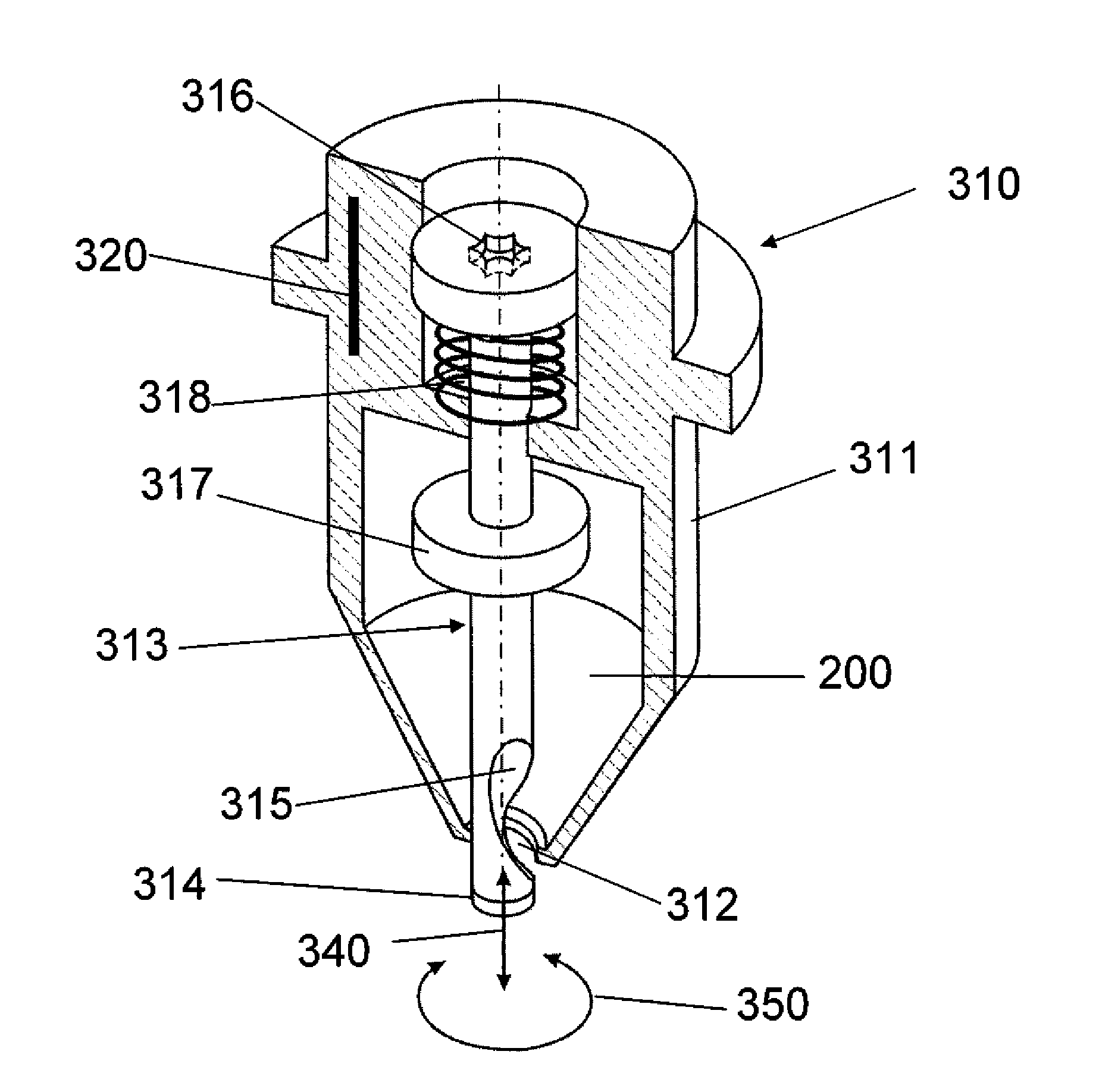
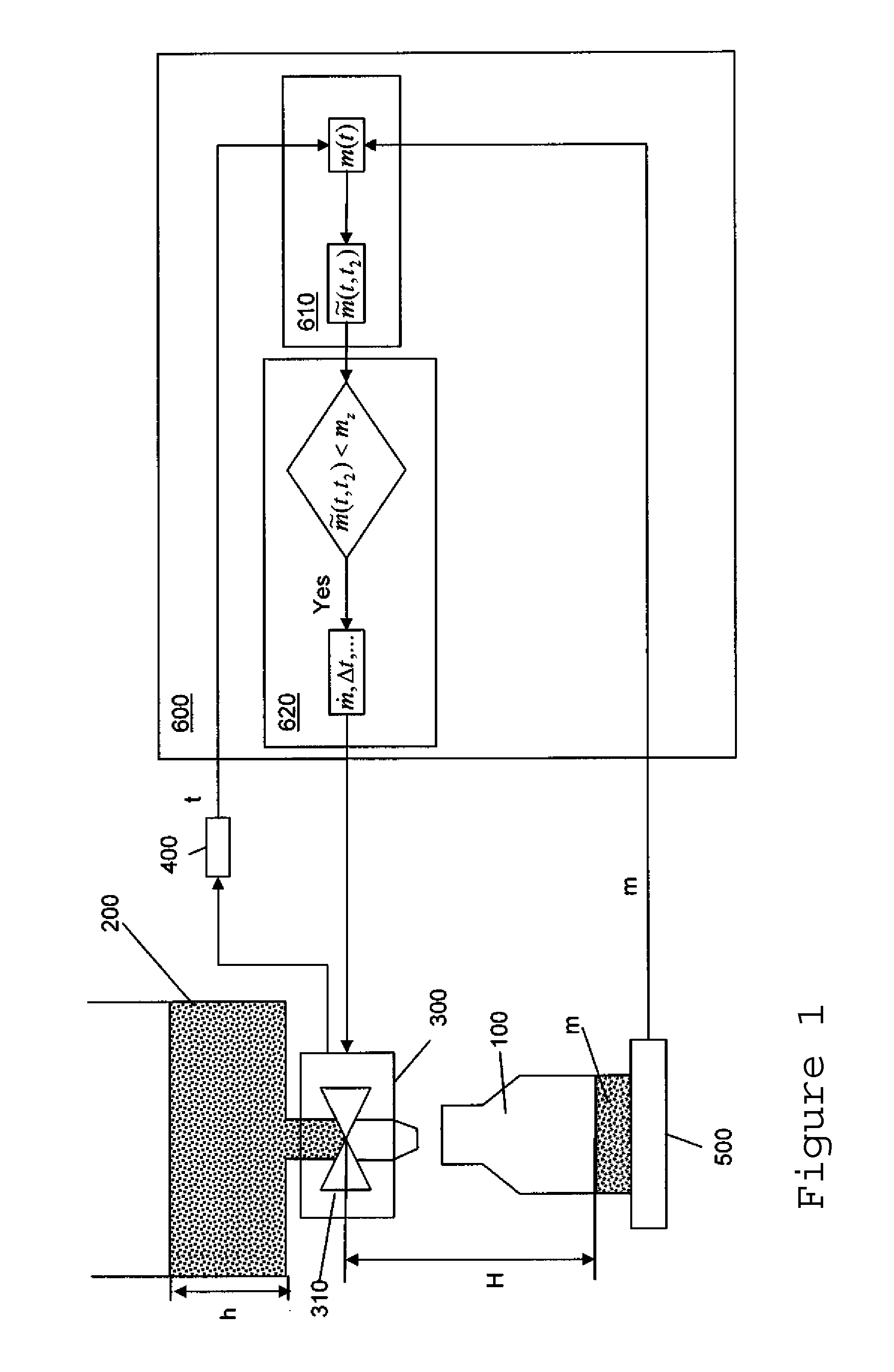
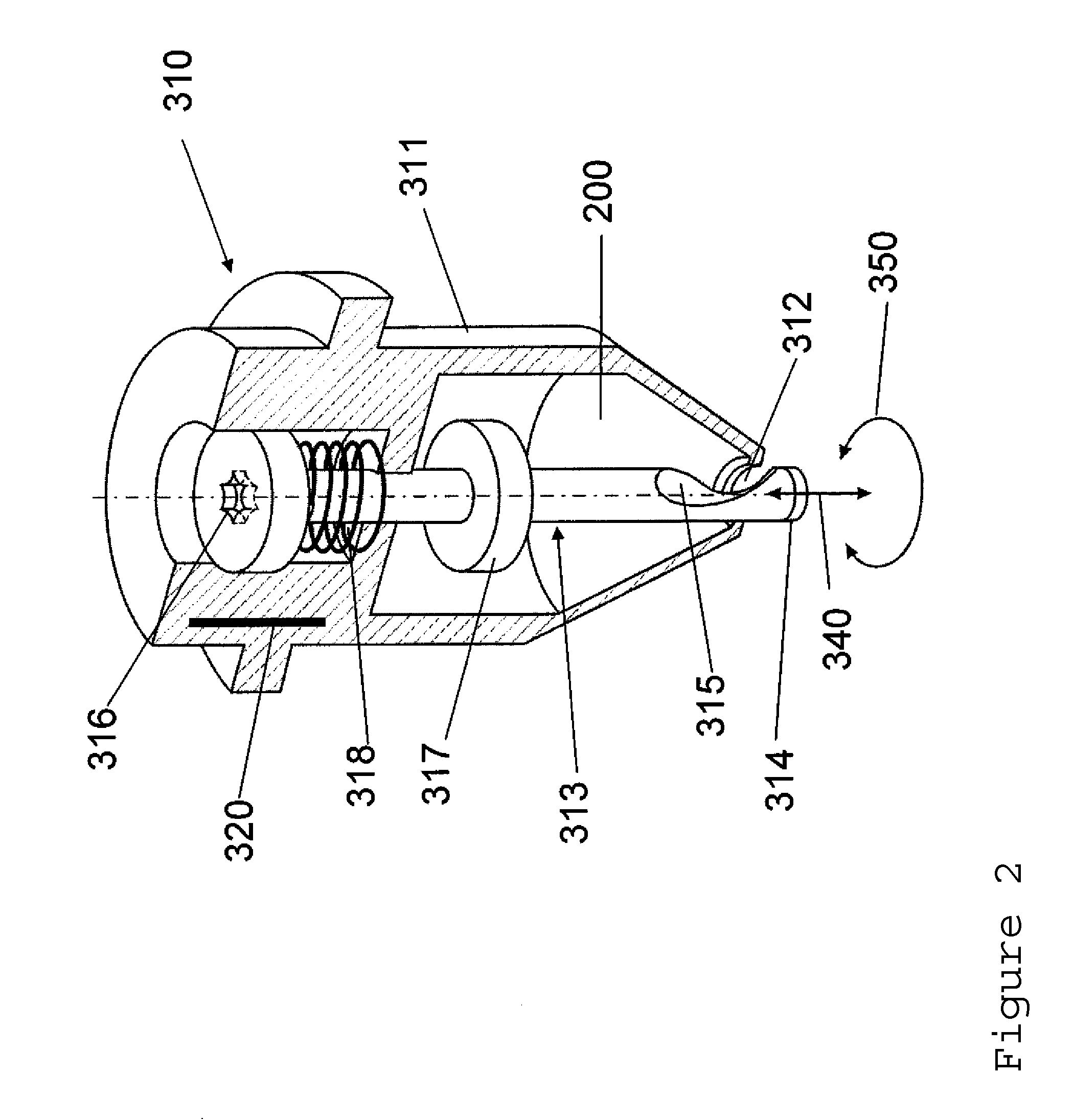
[0046]FIG. 1 illustrates a receiving container 100 which can be filled by way of a dosage-dispensing device 300 with a substance held in the reservoir 200 up to the fill level h. The dosage-dispensing device 300 is tied to a timing device 400 whereby the elapsed time from the start of the fill cycle can be determined and the signal representing the measured time can be transmitted to a controller unit 600. The receiving container is arranged on a balance 500, so that the weight of the substance that is present in the receiving container 100 can be determined. The signal representing the measured weight or mass can likewise be transmitted to the controller unit 600. In the controller unit 600, the time signal and the mass signal are tied to each other, so that the result represents the mass m(t) which is present at a certain elapsed time t from the start of the dosage-dispensing cycle.

[0047]Ideally, the valve 310 would be opened up more and more until the receiving container 100 hold...


PUM

PropertyMeasurementUnit
massaaaaaaaaaa
mass flow rateaaaaaaaaaa
timeaaaaaaaaaa

Abstract

A receiving container is filled with a predetermined target mass mz of a free-flowing substance from a reservoir with the help of a dosage-dispensing device that dispenses measured doses of the substance. The device has a valve for variably setting the mass flow {dot over (m)} from the reservoir into the receiving container. The device is also able to determine the time t that has elapsed since the beginning of the fill cycle, the mass m of the substance present in the receiving container, and a unit for controlling the valve. The controller unit includes estimating and correction modules. At least once during the fill cycle, the estimating module performs an estimate of the mass {tilde over (m)}(t, t2) that is expected to be present in the receiving container at the end of the fill cycle at the time t2. This estimate is based on the assumptions that from the time t onward the valve is being closed according to a predefined closing-down profile and the fill cycle is completed at the time t2. The correction module compares the mass {tilde over (m)}(t, t2) estimated at the time t to the target mass mz. If the estimated mass {tilde over (m)}(t, t2) is smaller than the target mass mz, the valve is controlled so that the aperture associated with the mass flow {dot over (m)} that exists at the time t will be maintained longer by a differential time segment Δt, and / or the mass flow {dot over (m)} at the time t is increased.

Description

CROSS-REFERENCE TO RELATED APPLICATIONS[0001]This application claims a right of priority under 35 USC §119 from European patent application 08 15 6708.3, filed 22 May 2008, the content of which is incorporated by reference as if fully recited herein.TECHNICAL FIELD[0002]The present invention concerns a method and a device to fill receiving containers, also referred to herein as target containers, with a predetermined target quantity of a free-flowing substance from a reservoir.BACKGROUND OF THE ART[0003]Filling devices of this kind are used in particular to dispense small dosage quantities which are needed for example in the pharmaceutical field. The receiving containers are often placed on a balance in order to weigh the mass of the substance delivered out of the dosage-dispensing device, so that the substance can subsequently be further processed in accordance with given specifications.[0004]The substance of which a measured dose is to be dispensed is held for example in a source ...

Claims


Application Information

Patent Timeline
Patent Type & Authority Applications(United States)
IPC IPC(8): B65B3/04B65B3/28
CPCG01G17/06
Inventor BLOCHLINGER, MARC
Owner METTLER TOLEDO GMBH
Why Eureka
Try Eureka