
DC power control to maximize battery charging time

a technology of power control and battery charging, applied in the direction of sequential battery discharge, transportation and packaging, battery arrangement for several simultaneous batteries, etc., can solve the problems of prolonging the battery operation life, reduce the maximum power output, reduce the charging/discharging cycle, and reduce the system cost

Inactive Publication Date: 2009-12-03
AMERICAN RELIANCE
View PDF14 Cites 43 Cited by
  • Summary
  • Abstract
  • Description
  • Claims
  • Application Information

AI Technical Summary

Benefits of technology

[0005]In accordance with an example of the present disclosure, the switch-matrix DC power control system manages total output power by combining power from the power source and power from the plurality of batteries under heavy load demand condition. Combining power from the power source and the batteries allows the system to use the power source with reduced maximum power output, reducing system cost. Under lighter load demand condition, the power source alone may power the load, and any excess power from the power source is used to charge the batteries. Using battery power only when the load requirement is greater than what the power source can supply reduces battery charging / discharging cycle, thus prolonging battery operational life.
[0006]In accordance with another example of the present disclosure, the switch-matrix DC power control system maximizes the amount of time the plurality of batteries is charging by controlling the charging and discharging of each battery independently. Each battery is by default in the charging state. The power control system monitors the input voltage at the load to control a switch matrix to dynamically discharge power from only those batteries required to drive the load. Independent charge / discharge control of each battery improves the efficiency of power transfer to the load and also prolongs battery operational life by maximizing charging time of the battery.

Problems solved by technology

Using battery power only when the load requirement is greater than what the power source can supply reduces battery charging / discharging cycle, thus prolonging battery operational life.

Method used


Image

  • DC power control to maximize battery charging time
  • DC power control to maximize battery charging time
  • DC power control to maximize battery charging time

Examples


Embodiment Construction

[0014]Systems and methods for improving power control in a switch-matrix DC power control system are disclosed. In a DC power control system, power sources such as solar arrays, wind turbines, hydroelectric generators, gas generators, or grid ties may be used to convert solar, wind, hydro, fossil fuel, AC electrical, or other forms of energy into DC electrical energy to drive a load.

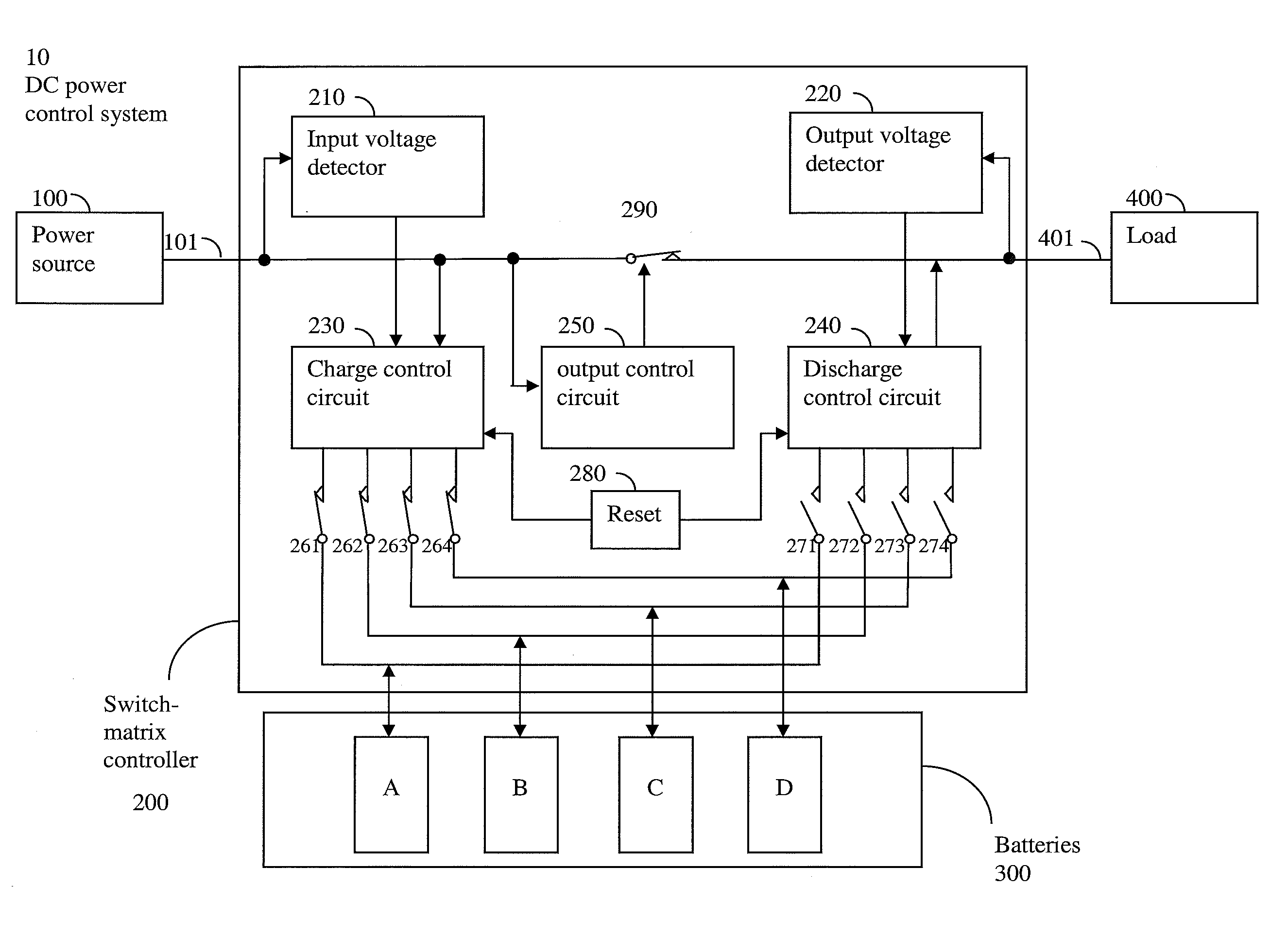
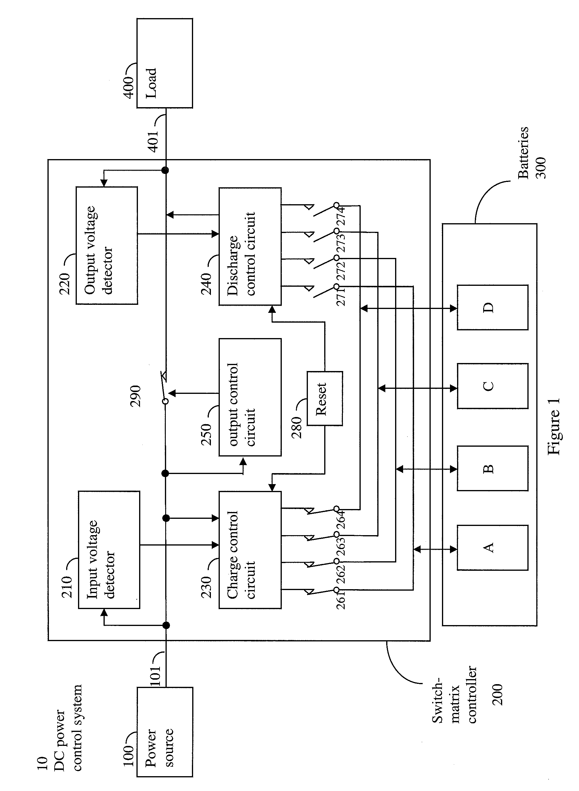
[0015]FIG. 1 is a block diagram of a DC power control system 10 having a power source 100, a switch-matrix controller 200, a plurality of batteries 300, and a load 400 according to one or more exemplary embodiments of the present disclosure. The power source 100, which can be, but is not limited to, a solar array, a wind turbine, a hydro power generator, a gasoline power generator, or a grid tie, generates electrical energy to build up a voltage level at a power source output 101. The switch-matrix controller 200 manages the transfer of electrical energy from the power source 100 to power the load 400, f...


PUM


Abstract

Systems and methods are provided for managing the batteries and the power source as a single combined output to power the load, allowing the system to use power source with reduced maximum power output, reducing system cost and complexity. Furthermore, the switch matrix controller efficiently and dynamically manages the internal power transfer to minimize the charging / discharging cycle of the batteries while ensuring that the power source and the batteries meet changing load power demand. Finally, maximizing charging time and having independent control of each battery increase power efficiency, prolong the operational life of the battery, and increase overall system life.

Description

TECHNICAL FIELD[0001]The present disclosure relates generally to power control systems. More particularly, the present disclosure relates to systems and methods for controlling power transfer in a DC (direct current) power system to maximize system power output, maximize battery charging time, and increase system life.BACKGROUND[0002]Conventional DC power systems include a power source, DC power controller, and batteries. Conventional DC power controllers are well known. They typically use quick-charge methods, voltage regulation / conversion, and / or battery protection to prolong battery operational life and to accelerate charging time. Typical systems utilize switches between the power source and the battery with a power controller pulse width modulating (PWM) the switches to achieve power transfer from the power source to the batteries. In such systems, the batteries are quickly charged by the power source, are discharged to power a load, and then are quickly charged again.[0003]Alt...

Claims


Application Information

Patent Timeline
IPC IPC(8): H02J7/34
CPCH02J7/0013H02J2007/0067H02J7/0022H02J7/0025
Inventor LI, FU YUCHEN, KALVIN
Owner AMERICAN RELIANCE
Learn More