Recording apparatus

a recording apparatus and recording head technology, applied in the direction of electric variable regulation, process and machine control, instruments, etc., can solve the problems of increasing power consumption during operation, reducing the efficiency of recording head, and undesirable to insert resistance components into the electrical route, so as to reduce the inrush current and prevent a sudden change in the power source voltage

Inactive Publication Date: 2009-12-03
CANON KK
View PDF16 Cites 22 Cited by
  • Summary
  • Abstract
  • Description
  • Claims
  • Application Information

AI Technical Summary

Benefits of technology

[0014]The present invention provides a recording apparatus that can reduce the inrush current when the

Problems solved by technology

For this reason, the instantaneous power consumption of the recording head is considerably large compared to the average power consumption thereof.
Recent recording apparatuses tend to have an increased number of nozzles and an increased driving speed to achieve faster and finer recording and also tend to consume increased power during operation.
However, when a low-impedance power source such that the power source voltage varies little when the electrical load varies is required, it is undesirable to insert a resistance component into the electrical route.
In order to detect the load current of the power source output, an expensive detecting circuit is necessary.
This increases the cost of the device.
However, since the recording apparatuses have a unit that controls turning on and off of the power supply to the recording head, an inrush current to the recording head can occur when the power supply is turned on after t

Method used


Image

  • Recording apparatus
  • Recording apparatus
  • Recording apparatus

Examples


first embodiment

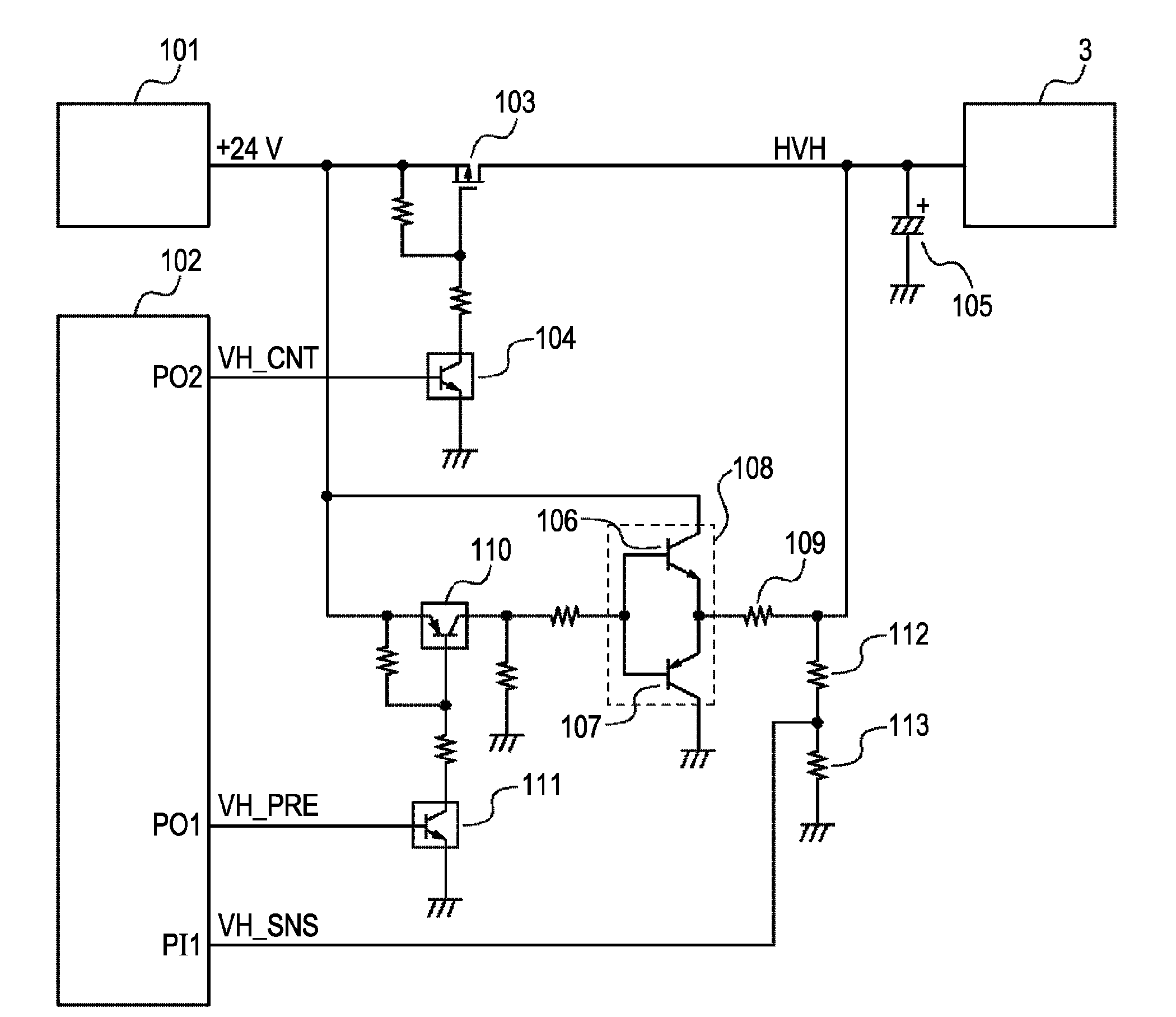
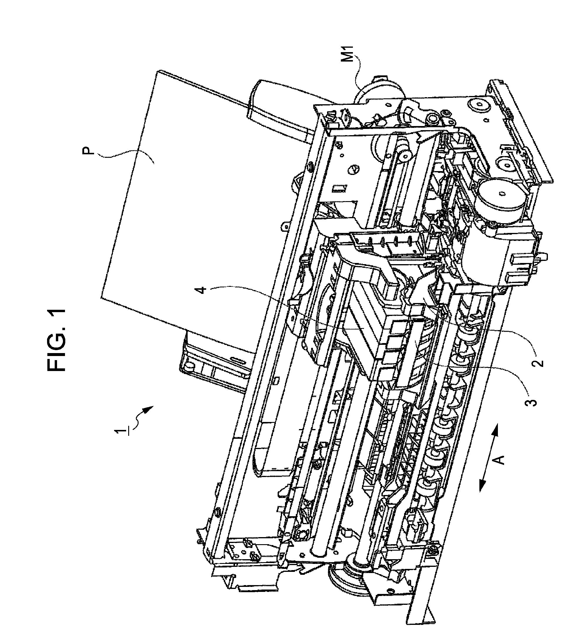
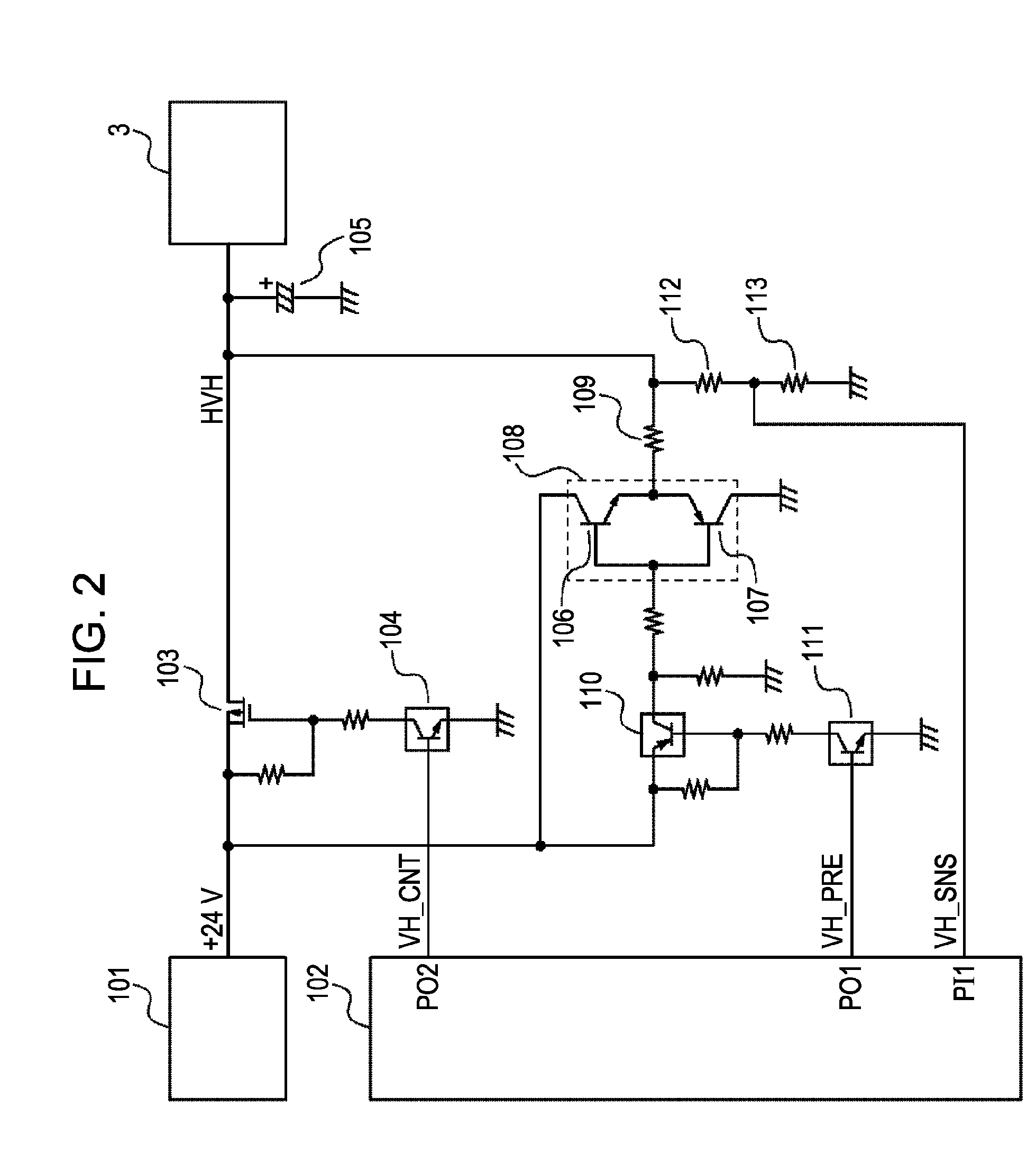
[0028]A first embodiment of the present invention will hereinafter be described with reference to the drawings.

[0029]FIG. 1 is an external perspective view showing the outline of the configuration of an ink jet recording apparatus 1 that is a typical embodiment of the present invention.

[0030]In the ink jet recording apparatus 1, the driving force of a carriage motor M1 is transmitted to a carriage 2 on which a recording head 3 is mounted, and the carriage 2 is reciprocated in the direction of arrow A. In addition, a recording medium P is conveyed to a recording position, where the recording head 3 ejects ink onto the recording medium P, thereby performing recording.

[0031]On the carriage 2 is mounted not only the recording head 3 but also ink cartridges 4 that contain ink to be supplied to the recording head 3. The ink cartridges 4 are detachable from the carriage 2.

[0032]The recording apparatus 1 shown in FIG. 1 is capable of color recording. For this purpose, the ink cartridges 4 i...

second embodiment

[0053]An ink jet recording apparatuses to which the present invention can be applied includes a battery pack that is a power supply device, and a printer connected to the power supply device. The battery pack is detachable from the recording apparatus.

[0054]In FIGS. 6A and 6B, reference numeral 11 denotes a battery case serving as a power supply unit that is attached to a printer 12 and supplies power to the printer 12. The battery case 11 has a battery pack therein that serves as a power source.

[0055]The battery case 11 is configured to be able to be easily attached to the exterior of the printer 12. The battery case 11 has a power switch 14 that works in conjunction with the movement of an upper cover 13 of the printer 12. Next, the function of this power switch 14 will be described.

[0056]First, as shown in FIG. 6A, when the printer 12 is not used, the upper cover 13 is closed and the power switch 14 is open. At this time, the power switch 14 turns off the power output of the batt...


PUM


Abstract

A recording apparatus includes an electrolytic capacitor for stabilizing the head power source voltage, a transistor for charging the electrolytic capacitor, a transistor for discharging the electrolytic capacitor, a push-pull circuit, a resistor for controlling the charging/discharging current to the electrolytic capacitor, and a resistor for dividing the head power source voltage. The power supply to the head is turned on with the head power source voltage increased by the capacitor.

Description

BACKGROUND OF THE INVENTION[0001]1. Field of the Invention[0002]The present invention relates to a recording apparatus, and more specifically, it relates to a recording apparatus having a unit that controls turning on and off of the power supply to a recording head.[0003]2. Description of the Related Art[0004]Current ink jet recording apparatuses have an ink jet head having many ink jet nozzles and select nozzles to eject ink according to print data. In such recording apparatuses, the number of nozzles to drive at the same time varies depending on print data, and the power consumed by the recording head also vary greatly. For this reason, the instantaneous power consumption of the recording head is considerably large compared to the average power consumption thereof. Of course, a power source that supplies power to the recording head needs to have a capacity to supply power that exceeds the power consumption of the recording head.[0005]Recent recording apparatuses tend to have an in...

Claims


Application Information

Patent Timeline
IPC IPC(8): B41J2/01
CPCB41J2/04541B41J2/04548B41J23/00B41J2/0457B41J2/0458B41J2/0455
Inventor NAKATA, KAZUHIRO
Owner CANON KK
Why Eureka
Try Eureka