
Reducing Maximum Power Consumption Using Environmental Control Settings

a technology of environmental control and maximum power consumption, applied in the direction of process and machine control, electrical apparatus casing/cabinet/drawer, instruments, etc., can solve the problems of power consumption of cooling fans must be factored into the total amount of power available to the computer system, and eight-fold increase in the power consumption of fans

Active Publication Date: 2009-12-03
LENOVO GLOBAL TECH INT LTD
View PDF29 Cites 81 Cited by
  • Summary
  • Abstract
  • Description
  • Claims
  • Application Information

AI Technical Summary

Benefits of technology

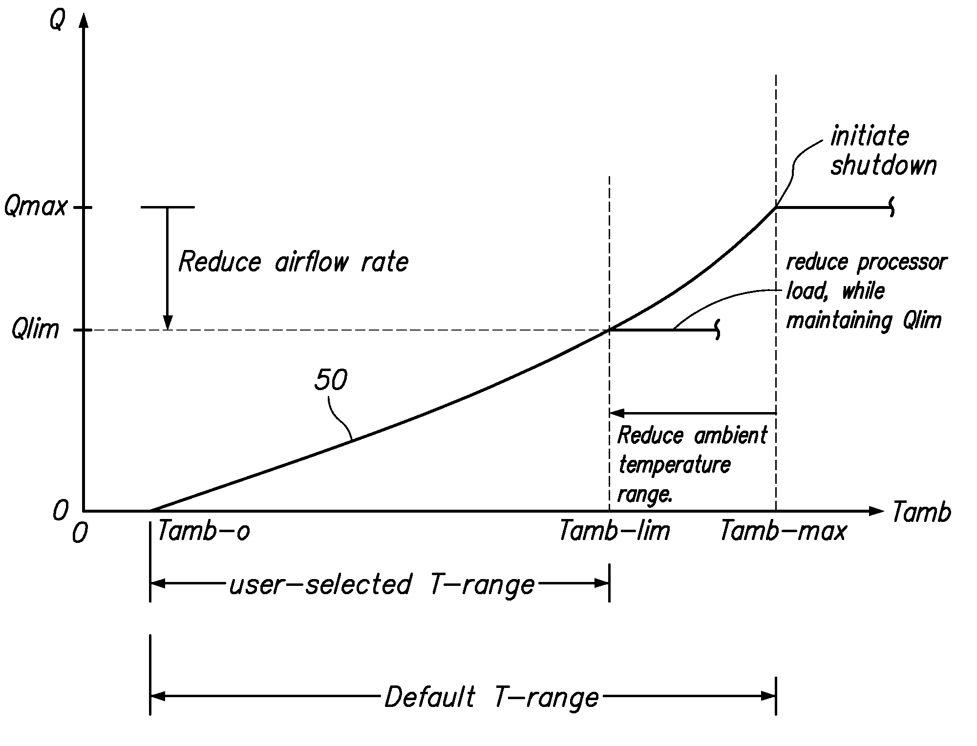
[0011]FIG. 3 is a graph plotting an exemplary fan performance curve defining the relationship between the detected ambient air temperature and the airflow rate to be enforced by the management system.

Problems solved by technology

Cooling fans consume power in addition to the power consumed by the components that are cooled by the cooling fans.
Thus, the power consumption of cooling fans must be factored into the total amount of power available to the computer system.
For example, the power consumption of a fan may be a cubic function of fan speed, such that doubling the speed of a fan can lead to an eight-fold increase in the power consumption of the fan.
Thus, for example, a computer system may be configured to operate the fans at maximum speeds under extreme ambient temperature conditions, in which case the fans may consume a large amount of power.
Other equipment such as power supplies and power cables may also be specified according to worst-case conditions, which increases the cost of the computer system.

Method used


Image

  • Reducing Maximum Power Consumption Using Environmental Control Settings
  • Reducing Maximum Power Consumption Using Environmental Control Settings
  • Reducing Maximum Power Consumption Using Environmental Control Settings

Examples


Embodiment Construction

[0013]The present invention includes one embodiment wherein default environmental parameters provided with a computer system may be changed by a user, and another embodiment wherein default environmental parameters may be changed at the factory. In either embodiment, the computer system may include a cooling system having a variable airflow rate and a management system for varying the airflow rate according to a defined relationship between the airflow rate and the ambient temperature. The defined relationship may be, for example, a table or equation referenced by the management system for selecting and enforcing an airflow rate at any given ambient temperature within a selected ambient temperature range. The ambient temperature range may be provided by default, such as by a system designer, to account for the wide ranging conditions the computer system is likely to encounter during operation. The upper limit of the ambient temperature range may then be reduced, to reduce the corres...


PUM


Abstract

A fan controller causes a fan assembly to flow air through a computer system at a variable airflow rate to cool the computer system. The ambient air temperature to the computer system is detected, and the controller varies the airflow rate as a function of the ambient temperature within an ambient temperature range having an upper limit. The upper limit on the defined ambient temperature range that is used by a fan speed control algorithm may be selectively reduced from a default value in response to electronic input, such from a user or a software object. Correspondingly, the controller limits the air flow rate to a reduced value corresponding to the reduced upper limit. The reduction in stranded power that results from reducing the upper limit on the ambient temperature may be re-allocated, such as to other racks in the data center.

Description

BACKGROUND OF THE INVENTION[0001]1. Field of the Invention[0002]The present invention relates to power management and cooling in a computer system, such as in a rack-mounted computer chassis.[0003]2. Description of the Related Art[0004]The cost to both power and cool a computer system are important considerations in the design, development, and operation of computer systems. Computer systems generate heat as a result of consuming electrical power, and typically require a cooling system to maintain acceptable internal operating temperatures. For example, in a rack-mountable computer system, fans are typically included, either in the rack-mounted components to be cooled or as part of a rack-mounted fan assembly, for generating airflow through the computer system. The airflow rate may be dynamically varied according to the cooling needs, which vary over time. The cooling needs may vary, for example, according to the load placed on electronic components and the corresponding power consu...

Claims


Application Information

Patent Timeline
Patent Type & Authority Applications(United States)
IPC IPC(8): G06F1/20
CPCG06F1/206Y02B60/1275H05K7/20836Y02D10/00
Inventor MATTESON, JASON AARONPIAZZA, WILLIAM JOSEPH
Owner LENOVO GLOBAL TECH INT LTD
Learn More