Light Strip

a technology of light strips and coatings, applied in the field of light strips, can solve the problems of affecting the performance of light strips, and affecting the appearance of light strips, etc., and achieve the effect of reducing manufacturing costs

Inactive Publication Date: 2009-12-03
TARKO NORM +1
View PDF8 Cites 9 Cited by
  • Summary
  • Abstract
  • Description
  • Claims
  • Application Information

AI Technical Summary

Benefits of technology

[0022]By providing light emitting diodes which are received within a light mounting aperture within a core layer and locating the conductive elements to lay flat against opposing sides of the core so that the LED's are received between the conductive elements, the open ends of the apertures can be enclosed by a thin and readily placed casing material applied in layers extending along the flat opposed sides of the core with the light emitting diodes being fully recessed and protected within the core between the conductive elements. Accordingly with minimum coating material the resulting strip is much narrower and includes no protruding components as compared to prior art configurations of light strips. Furthermore, the core layer and the cover layer can be formed of readily available preformed strips of material so that no new molding dies are required and manufacturing cost is a minimum.

Problems solved by technology

Accordingly it is awkward to adequately seal and protect the lights protruding from the flat plane of the conductive elements unless a particularly large surrounding casing of material fully surrounds all of the conductive elements and the light emitting diodes, resulting in a relatively wide strip compared to the individual components thereof which further requires a relatively large amount of casing material to fully surround and protect the components.
Furthermore application of a coating typically requires application at high temperature and pressure to the LED's already mounted in connecting with conductive elements.
The heat and pressure of applying the coating such that the coating bonds well can be very damaging to the small conductive connections and small components of the light strip.
U.S. Pat. No. 5,559,681 by Duarte discloses a modular lighting system comprising flexible strips of lights in which the lights are somewhat protected within a surrounding housing, however the light strip requires formation of multiple individual components which are uniquely molded in shape such that manufacturing can be comparatively expensive and assembly can be awkward and difficult to automate.
Furthermore recessing the lights within surrounding strips of material requires a plurality of individual lenses to be mounted in the upper layer where the lenses then protrude from the top surface of the light strip such that any pressure applied to the light strip is concentrated on the protruding components which can result in damage to the lights mounted within the housing.
The resulting structure is quite large and complex, and accordingly is much more expensive to manufacture than the light strips noted above such that it is not particularly relevant to efficient manufacturing of a low cost light strip as in the present invention.

Method used


Image

  • Light Strip
  • Light Strip
  • Light Strip

Examples


Embodiment Construction

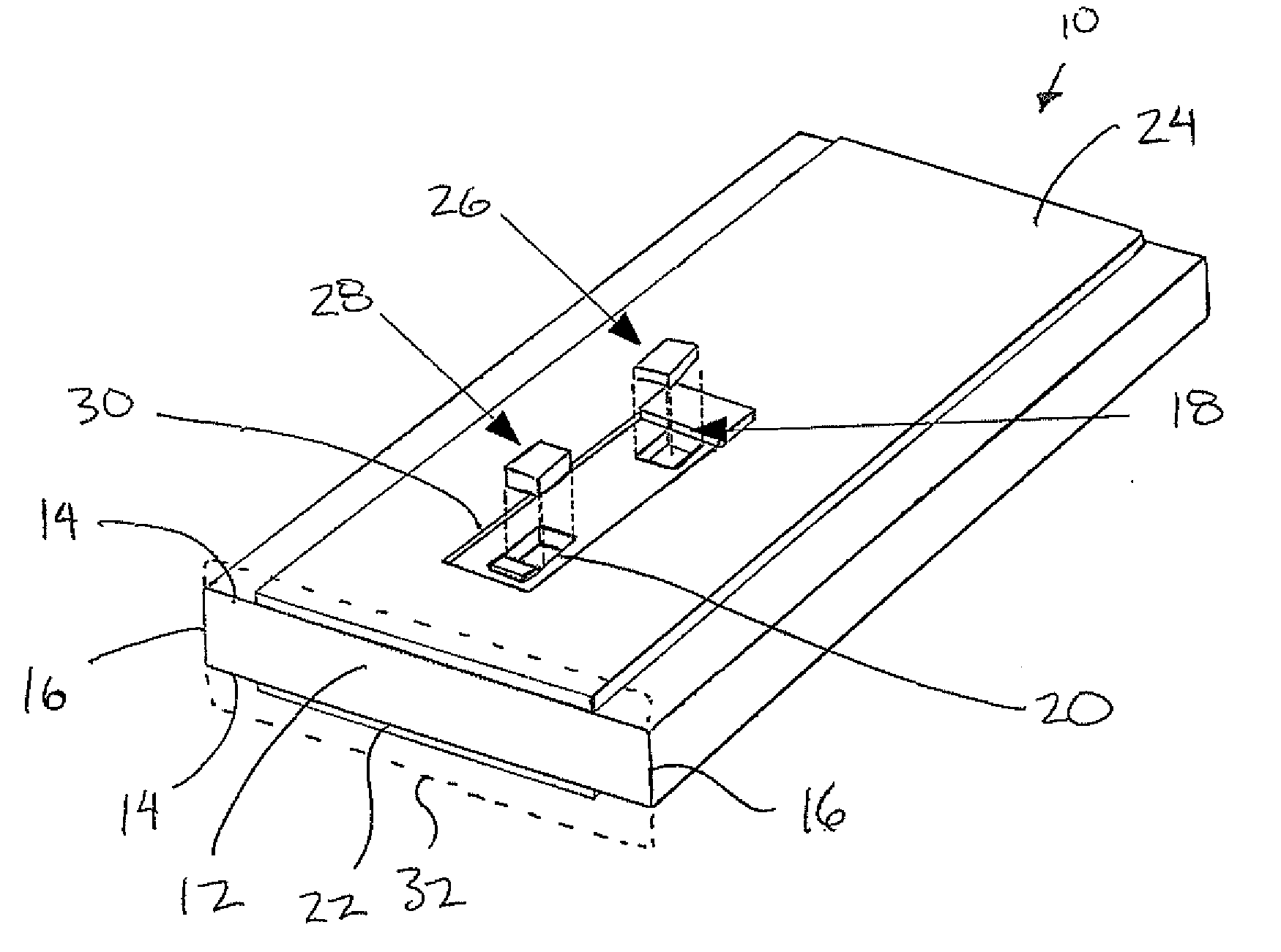
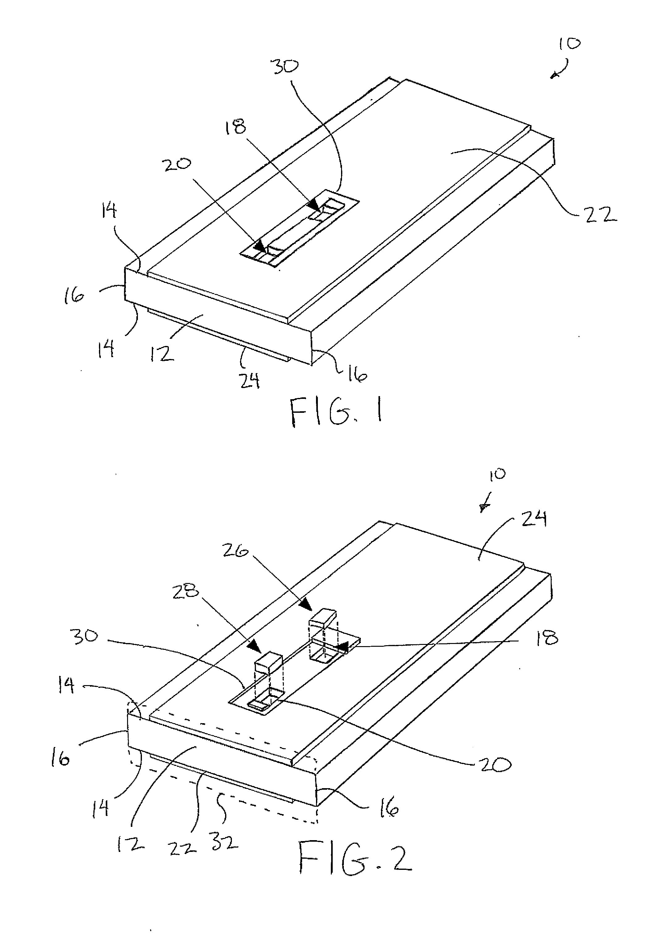
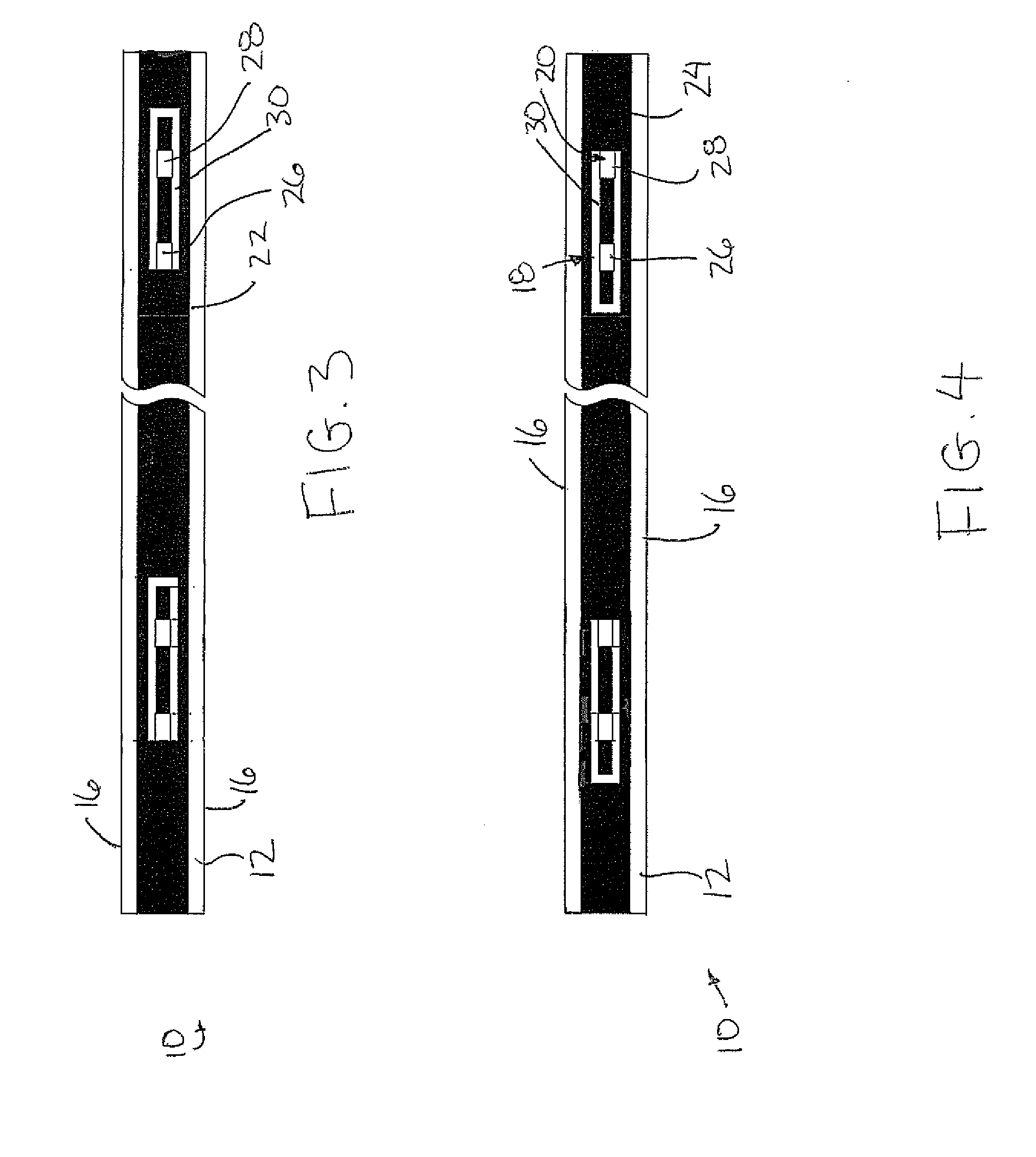
[0066]Referring to the accompanying FIGS. 1 though 4 there is illustrated a light strip generally indicated by reference numeral 10. The strip 10 includes a core which forms the main body of the light strip. The core 12 extends in a longitudinal direction of the light strip and has a generally rectangular cross section defining two flat opposed faces 14 which extend in the longitudinal direction of the core and two much narrower edges 16 spanning between the two faces 14 along opposing edges thereof. The height of the edges 16 corresponding to the space between the two opposed faces 14 is much smaller than the overall width of the faces in a lateral direction between the two edges 16 so that the lateral width of the faces 14 is plural times greater than the space between the two faces as defined by the height of the edges 16.

[0067]The core 12 is elongate and formed of insulating material such as a polymer for example.

[0068]A plurality of light mounting apertures 18 are provided at s...


PUM


Abstract

A light strip comprises an elongate core layer of insulating material having a plurality of light mounting apertures extending through the core layer between the two opposed faces of the core layer and receiving respective light emitting diodes therein. Two conductive elements extending in the longitudinal direction along the outer surface of the elongate core layer between which the light emitting diodes are connected. A cover layer spans in the longitudinal direction adjacent each one of the two opposed faces of the elongate core layer to enclose opposing ends of the light mounting apertures with the light emitting diodes therein.

Description

[0001]This application claims the benefit under 35 U.S.C. 119(e) of U.S. provisional application Ser. No. 61 / 057,063, filed May 29, 2008.FIELD OF THE INVENTION[0002]The present invention relates to a light strip of the type comprising a plurality of light emitting diodes connected at longitudinally spaced positions between a pair of longitudinally extending conductive elements, and more particularly relates to a method of forming the light strip.BACKGROUND[0003]Light strips comprising a plurality of lights supported at spaced positions along an elongate strip are known to be desirable in many locations, for example for aesthetics, for highlighting an edge or for illuminating the perimeter of an object for example. Light emitting diodes (LED's) are commonly used where it is desirable to consume minimal electrical power with minimal manufacturing cost. A typical construction involves two conductive bands supported in a common plane with light emitting diodes connected in parallel betw...

Claims


Application Information

Patent Timeline
Patent Type & Authority Applications(United States)
IPC IPC(8): F21S4/00H01L21/50
CPCF21Y2101/02F21S4/005F21S4/22F21Y2115/10Y10S362/80
Inventor TARKO, NORMWANG, PEI
Owner TARKO NORM
Why Eureka
Try Eureka