
Method and system for volumetric displacement

a volumetric displacement and volumetric technology, applied in the field of volumetric displacement methods and systems, can solve the problems of limited foam production, difficult to produce volumetric portions, and difficult to achieve volumetric volumetric production, etc., and achieve the desired operating speed of packaging, control simplicity, and high accuracy

Inactive Publication Date: 2011-07-07
PACKLINE
View PDF17 Cites 4 Cited by
  • Summary
  • Abstract
  • Description
  • Claims
  • Application Information

AI Technical Summary

Benefits of technology

[0033]The new method according to the present invention for cyclically portioning liquids and pastes by displacing required volume provides the technical base for a variety of “Volumetric Copying Devices” and / or “VCD” which will provide end-users with control simplicity, high accuracy and desired operating speed of packaging and the significantly smaller sizes and lower prices.
[0034]The object of the present invention is to provide this new volumetric method for portioning liquids and pasted products at a required rate of operating speed, for example, in the range of 60 portions per minute, and with a minimum excess of the product over the predetermined target volume in order to minimize “give-away” losses, or for otherwise best matching the predetermined target volume, including the cases then the target of a portion can be changed from cycle to cycle in preset limits, and at minimal manufacturing cost of the dosing machine.

Problems solved by technology

It is virtually impossible, from a practical standpoint, to produce portions with volumes exactly according to a specified targeted volume, and therefore machines generally produce portions with excess volumes over the target volume.
Although this type of filler is used predominantly on products that do not foam, foam may be limited and controlled by subsurface / bottom-up fill capability.
Hazardous location means that there is risk of explosion or auto-ignition of the products being filled.
But sometimes the products being filled are so aggressive that special construction methods are required.
In both cases, even the factory air alone contributes to the accelerated degradation of the machinery.
It should be noted that there is no ideal combination of materials in a filling machine when it comes to corrosive filling.
Avoidance of some metal components is impossible particularly in the case of fasteners.

Method used


Image

  • Method and system for volumetric displacement
  • Method and system for volumetric displacement
  • Method and system for volumetric displacement

Examples


Embodiment Construction

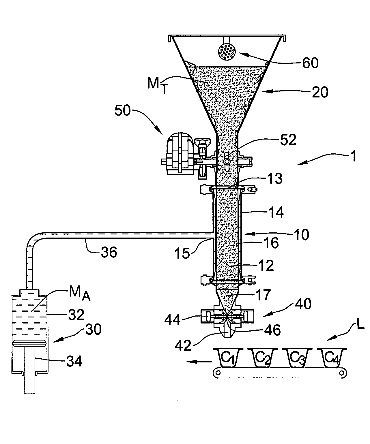
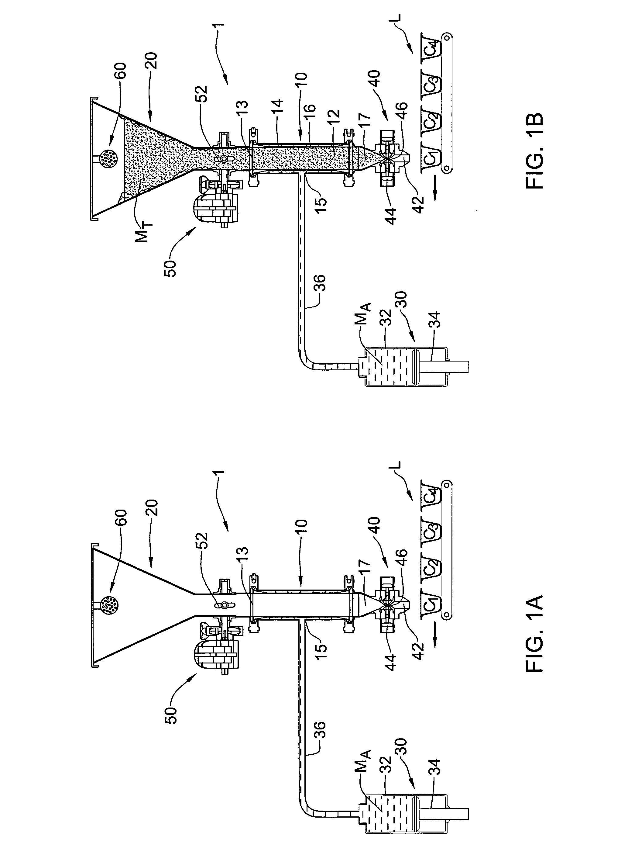
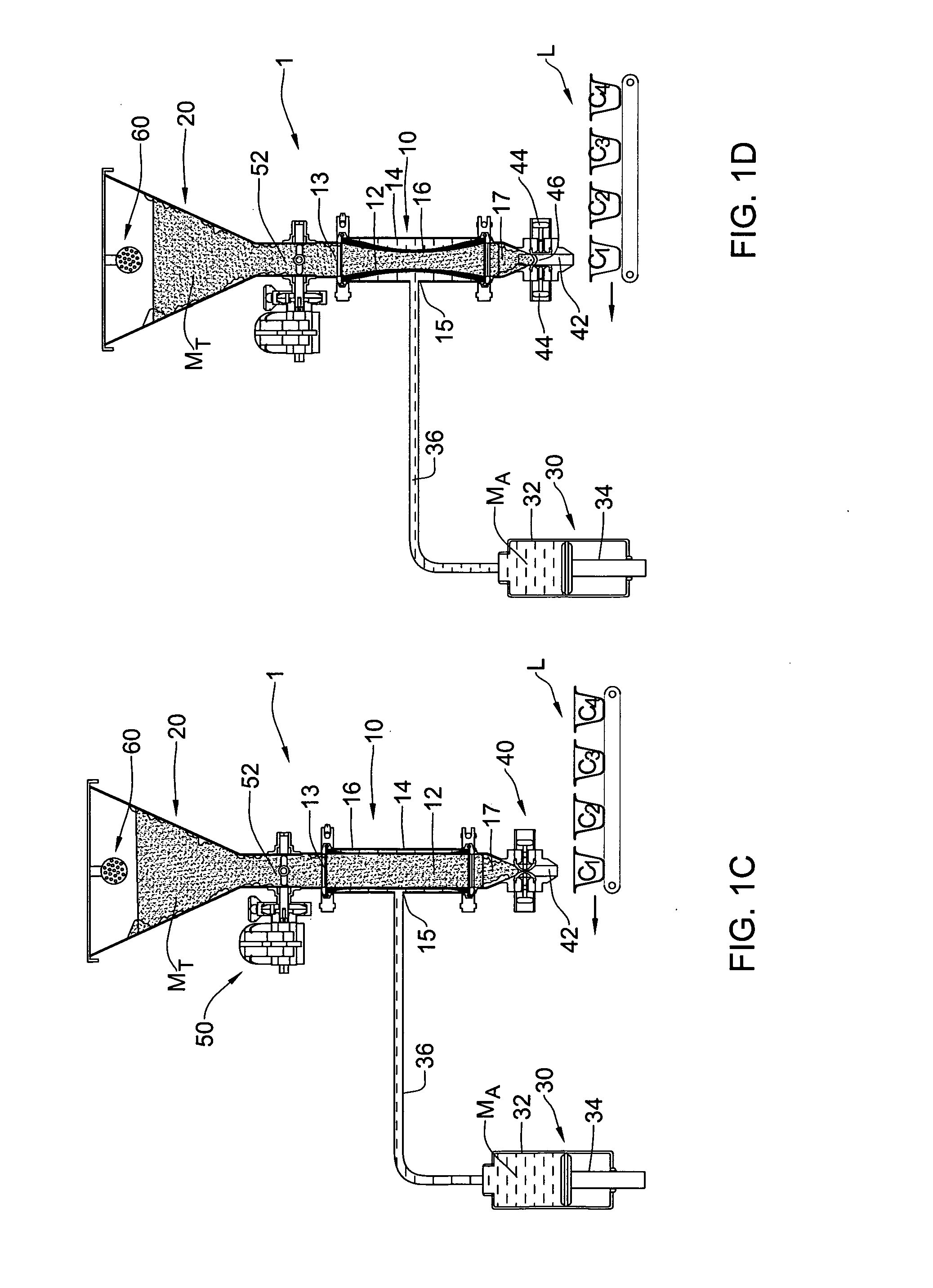
[0082]With reference to FIGS. 1A to 1H, a filling system is shown, generally designated as 1 adapted for working in conjunction with a filling line L. The system comprises a control volume portion 10, a target material storage 20, an auxiliary material mechanism 30, an outlet assembly 40, a controller unit 50, and a cleaning arrangement 60.

[0083]The control volume portion 10 comprises a target material compartment 12 and an auxiliary material compartment 14, sealingly separated from one another by a resilient diaphragm 16 adapted to deform so as to selectively change the volume of one compartment on the expense of the other compartment. The control volume 10 has a volume V0 which is constituted at all times by the combined volume V1 of the target material compartment 12 and volume V2 of the auxiliary material compartment 14.

[0084]The control volume 10 is formed with a first inlet port 13 located at a top end thereof and being in fluid communication with the storage 20 to receive a t...


PUM

PropertyMeasurementUnit
Pressureaaaaaaaaaa
Volumeaaaaaaaaaa
Mechanical propertiesaaaaaaaaaa

Abstract

Provided is a method for volumetric displacement of a predetermined desired volume ΔV of target material from a first location to a second location. The method including: (a) providing a rigid control volume having a V0 accommodating a resilient volumetric member coaxially located therein having a target material chamber of volume V1. The target material chamber is confined by an inner surface thereof, and constitutes the first location. The control volume V2 confined between an outer surface of the resilient volumetric member and an inner surface of the rigid control volume. The control volume further includes at least a target material outlet; (b) filling the target material chamber with the target material; (c) introducing a predetermined desired volume ΔV of an incompressible auxiliary material into the auxiliary material chamber to apply pressure to the resilient volumetric member. Thus, there occurs increasing of the volume of the auxiliary material chamber V2 to V2′=V2+ΔV and consequently reducing of the volume of the target material chamber from V1 to V1′=V1−ΔV; and (d) allowing a predetermined amount ΔV of target material to exit the target material chamber through the target material outlet to the second location.

Description

FIELD AND BACKGROUND OF THE INVENTION[0001]This present invention relates to a method and an apparatus for the cyclical volumetric portioning of liquids and pasted products based on the predetermined target volume, i.e., for cyclically producing, during each cycle, portions of the dosed product best matching the predetermined target volume. The invention is particularly useful for portioning high viscosity, corrosive and aggressive liquid products used in chemical and food industries, and is therefore described below with respect to such applications.[0002]Packing and / or filling machines must operate at a required speed, and must also include, in each package or a container, at least a minimum volume or weight of a dosed product specified on a package or container, hereinafter referred to as the predetermined target volume. It is virtually impossible, from a practical standpoint, to produce portions with volumes exactly according to a specified targeted volume, and therefore machine...

Claims


Application Information

Patent Timeline
IPC IPC(8): B67D7/08
CPCG01F11/088G01F11/021
Inventor KATSELI, VICTOR
Owner PACKLINE
Learn More