Hydrostatic machine with compensated sleeves

a technology of hydraulic machine and compensating sleeves, which is applied in the direction of mechanical equipment, engines without rotary main shafts, engines with rotating cylinders, etc., can solve the problems of increased friction energy and heat generation resulting from increased friction energy, and achieves easy manufacture and assembly, simple structure, and easy operation.

Inactive Publication Date: 2006-07-11
HYDROMATIK GMBH
View PDF13 Cites 5 Cited by
  • Summary
  • Abstract
  • Description
  • Claims
  • Application Information

AI Technical Summary

Benefits of technology

[0014]For reasons of simple manufacture and assembly, it is advantageous to form the recess as an annular recess. Such a configuration is easy to manufacture by a rotational movement of the sleeve and also when assembling the sleeve it is not necessary to place it in a specific position with regard to its circumferential direction.
[0015]In addition, it is advantageous to form the recess with the cross section rounded, in order to avoid material breakage due to delicate corners or edges.

Problems solved by technology

On the one hand, the friction energy and the heating resulting thereby are increased by high relative velocities between the pistons and the sleeves.

Method used


Image

  • Hydrostatic machine with compensated sleeves
  • Hydrostatic machine with compensated sleeves
  • Hydrostatic machine with compensated sleeves

Examples


Embodiment Construction

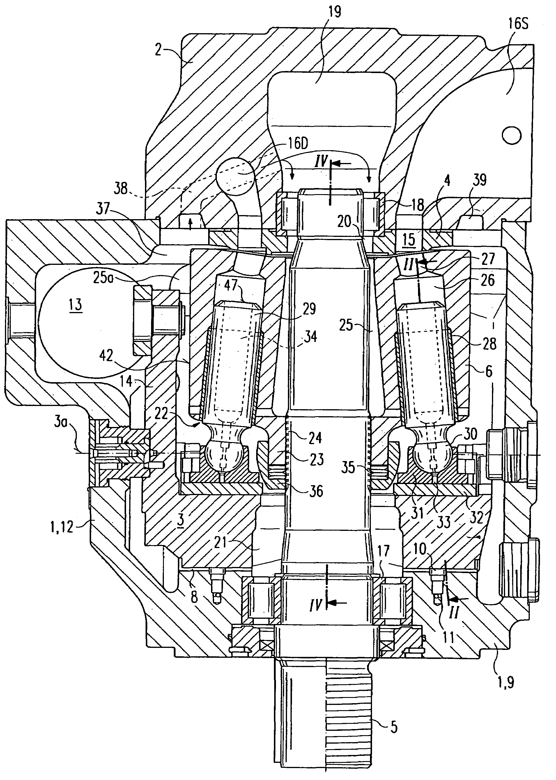
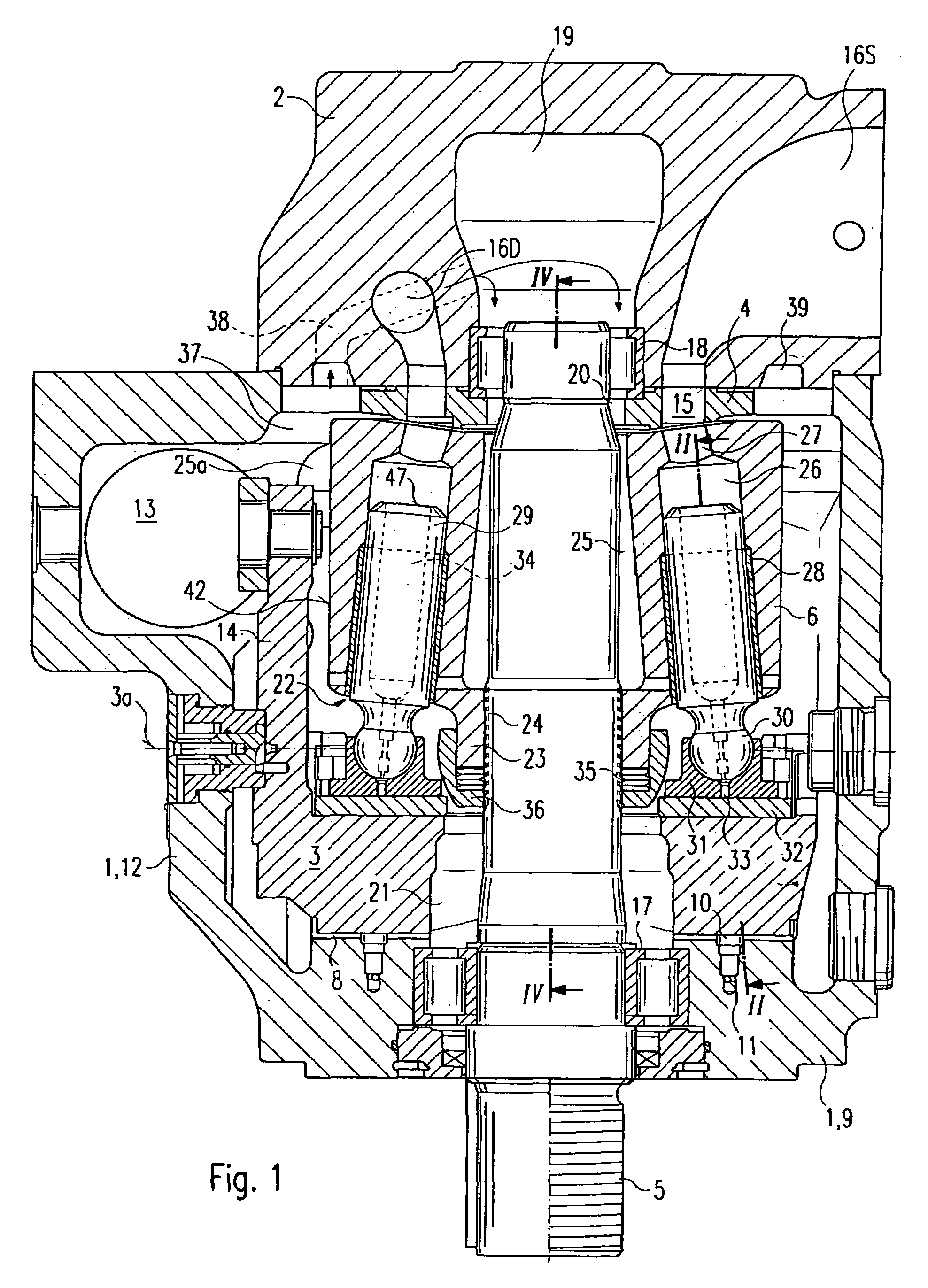
[0024]The axial piston machine illustrated in FIGS. 1 and 4 is of swash plate construction having adjustable displacement volume and includes in a known manner as main components a hollow cylindrical housing 1 having one end (upper end in FIG. 1) open at the end face, a connection block 2 attached to the housing 1 and closing the open end of the housing, a swash plate 3, a control body 4, a drive shaft 5 and a cylinder drum (cylinder block) 6. The axial piston machine can also within the scope of the invention concern a constant machine. In addition, the axial piston machine can be equipped for pumping and / or motor operation and / or for operating in alternating directions of rotation.

[0025]The swash plate 3 is formed as so-called tilting rocker with half-cylindrical cross section and bears with two bearing surfaces extending parallel to the tilt direction and with mutual radial spacing, under hydrostatic balancing on two correspondingly formed bearing shells 8, which are attached to ...


PUM


Abstract

A hydrostatic machine with a cylinder block (6), within which sleeve holes (28b) are arranged, in which sleeves (28) sit, surrounding piston bores (28a) in which pistons (29) are mounted, such as to be displaced back and forth and the pistons (29) extend into the cylinder block (5) such as to define cylinders (26) with the front ends thereof. According to the invention, the risk of piston seizure can be reduced, whereby the sleeves (28) comprise an axially-defined recess (41) in the outer surface thereof, in the region facing away from the cylinder and the region with the greatest piston radial force, pressing the pistons (29) against the wall of the piston bore.

Description

BACKGROUND OF THE INVENTION[0001]1. Field of the Invention[0002]The invention relates to a hydrostatic machine.[0003]2. Discussion of the Prior Art[0004]A hydrostatic machine of such kinds is described in DE 44 23 023 A1. In the case of this previously-known hydrostatic machine, the sleeves, in order to avoid piston seizure, are cooled with a cooling flow of the hydraulic fluid, which flows during operation through a respective cooling channel, which roughly radially extends outwards from the leakage chamber in a central hole of the cylinder block and opens out into the leakage chamber outside the cylinder block. The respective cooling channel extends through an inner annular groove in the wall of the sleeve hole seating the associated sleeve or through an inner annular groove in the inner surface of the sleeve. This previously-known cooling method worked satisfactorily in practice, but it is complex since each sleeve must be connected to the radial cooling channel, for the purpose ...

Claims


Application Information

Patent Timeline
Patent Type & Authority Patents(United States)
IPC IPC(8): F01B3/00F04B15/00
CPCF01B3/0044F04B15/00F01B3/0052
Inventor DONDERS, STEVEN
Owner HYDROMATIK GMBH
Why Eureka
Try Eureka