Chain reaction control circuit for parallel power supply

a control circuit and power supply technology, applied in emergency protective arrangements, liquid/fluent solid measurement, instruments, etc., can solve the problems of high manufacturing cost, difficult to overcome size and heat dissipation problems, and difficult to meet the requirement of a greater power supply capacity through a single power supply. achieve the effect of optimizing the benefits of higher and lower power combinations, high capacity power supply structures, and low manufacturing costs

Inactive Publication Date: 2005-11-10
ZIPPY TECH
View PDF7 Cites 4 Cited by
  • Summary
  • Abstract
  • Description
  • Claims
  • Application Information

AI Technical Summary

Benefits of technology

[0007] Therefore the primary object of the present invention is to resolve the aforesaid disadvantages. The invention aims to provide a high capacity power supply structure without altering the design of the original power supply. A control unit is provided to perform signal distributing function. The number of signal output legs correspond to the parallel number of the power supply, and the power supply may be couple

Problems solved by technology

For the power supply vendors, trying to meet the requirement of a greater power supply capacity through a single power supply involves complicated techniques.
It results in higher manufacturing cost.
The size and heat dissipation problems also are difficult to overcome.
Moreover, in the event that all of the hardware equipment is not being fully utilized during computer operation, electric power resource is wasted.
The power supply of different vendors has compatibility problem.
This incompatibility problem even occurs to the power supply of different models purchased at different time.
It is not economical.
In the event that two sets of power supply cou

Method used


Image

  • Chain reaction control circuit for parallel power supply
  • Chain reaction control circuit for parallel power supply
  • Chain reaction control circuit for parallel power supply

Examples


Embodiment Construction

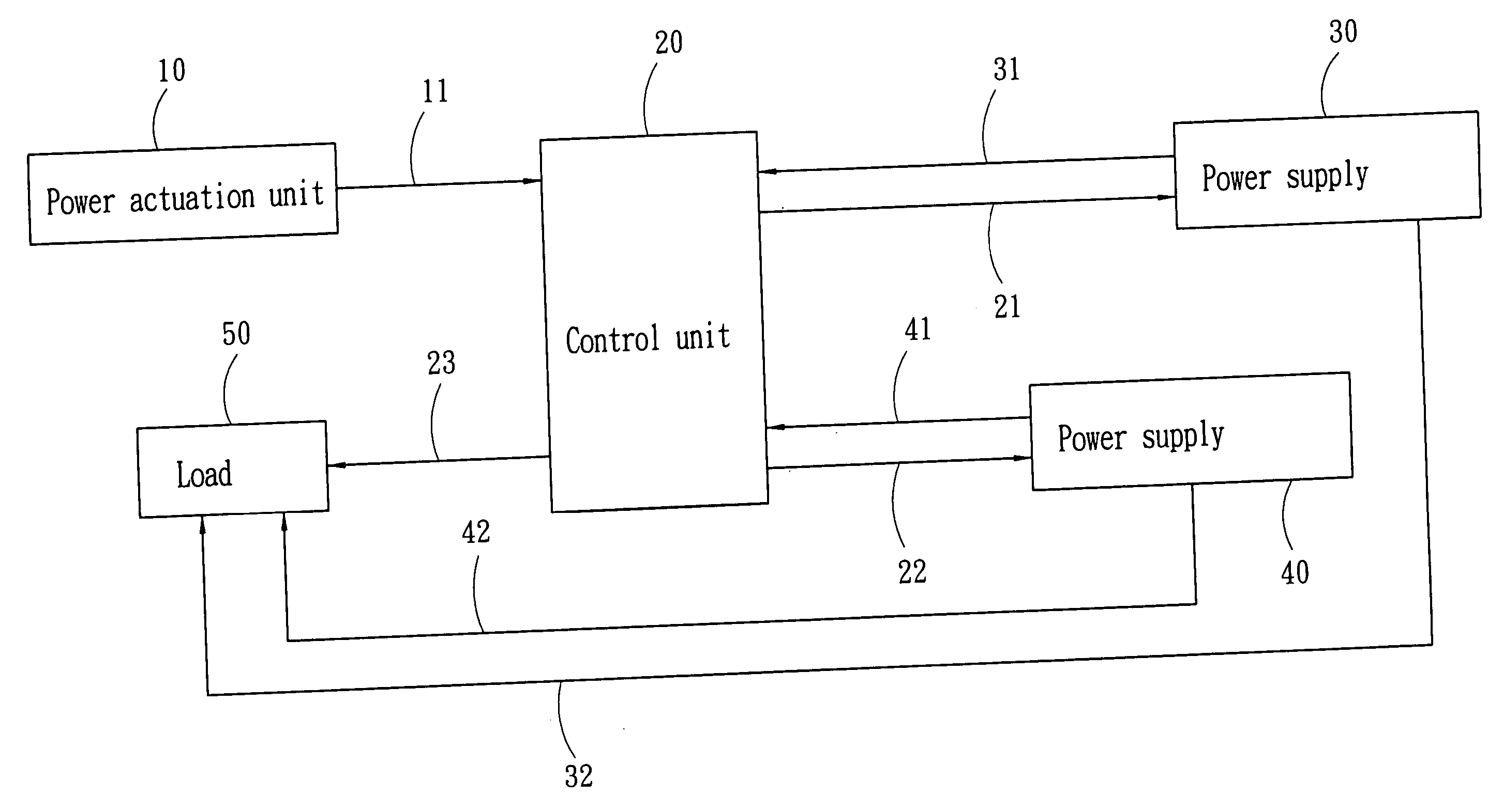
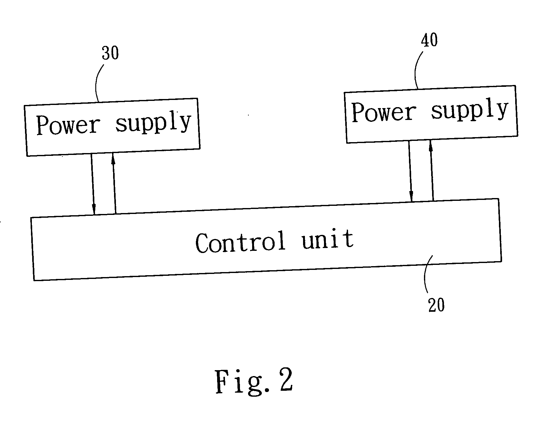
[0014] Please refer to FIGS. 2 and 3 for the coupling and circuit block diagrams of the invention. The invention includes a chain reaction control circuit for parallel power supply 30 and 40. The chain reaction control circuit includes a power actuation unit 10 to output a first power actuation signal 11 to activate electric power output, a control unit 20 to receive the power actuation signal and output a plurality of second power actuation signals 21 and 22, and the parallel power supply 30 and 40 that receive the second power actuation signals 21 and 22 and perform electric power transformation to output electric power 32 and 42. The power supply 30 and 40 also output respectively a first power confirmation signal 31 and 41 to the control unit 20 when the transformation of the electric power 32 and 42 has finished, and the control unit 20 receives the first power confirmation signals 31 and 41 and outputs a second power confirmation signal 23 to a linked load 50, and the power su...


PUM


Abstract

A chain reaction control circuit for parallel power supply provides greater power without changing the design of the original power supply structure. It includes a control unit to receive a first power actuation signal output from a power actuation unit, then output multiple sets of second power actuation signals to parallel power supplies. The multiple power supplies that are coupled in parallel receive the second power actuation signals and transform electric power simultaneously, then output electric power. After the electric power transformation has been finished, first power confirmation signals are output from the power supplies to the control unit which receives the first power confirmation signals and outputs a second power confirmation signal to a linked load. And the power supplies supply the corresponding and matching electric power to a linked load.

Description

FIELD OF THE INVENTION [0001] The present invention relates to a chain reaction control circuit for parallel power supply and particularly to a control circuit adopted for use on a plurality of parallel power supplies of same or different power specifications to simultaneously activate electric power transformation to output electric power. BACKGROUND OF THE INVENTION [0002] With flourishing developments of multimedia technologies, many personal computers or servers are equipped with more hardware equipment (such as hard disk drive, card reader, compact disc burner and the like) to improve performance. Due to the power supply for the original hardware configuration has a fixed power capacity, when the added hardware equipment exceed the original power supply limitation, users have to procure a power supply of a greater capacity to meet the operation requirement. For the power supply vendors, trying to meet the requirement of a greater power supply capacity through a single power sup...

Claims


Application Information

Patent Timeline
IPC IPC(8): G06F1/26H02H7/00H02J1/10H02J7/00H02M1/36
CPCG06F1/263H02M1/36H02J1/102H02J1/10
Inventor CHEN, TSUNG-CHUNLEE, TSUNG-TE
Owner ZIPPY TECH
Why Eureka
Try Eureka