Scroll fluid machine

a fluid machine and roller technology, applied in machines/engines, liquid fuel engines, couplings, etc., can solve the problems of galling and wear of the sliding portion, difficult to increase the length of the movable plate, and reduce the width, so as to reduce the noise of sliding, reduce the loss of sliding, and suppress the wear and damag

Inactive Publication Date: 2009-12-03
RICHSTONE
View PDF3 Cites 1 Cited by
  • Summary
  • Abstract
  • Description
  • Claims
  • Application Information

AI Technical Summary

Benefits of technology

[0007]Accordingly, it is an object of the invention to provide a scroll fluid machine for reducing the sliding loss of the component of the anti-self rotation mechanism for the eccentric shaft to suppress the wear, damage, and sliding noise.
[0015]The scroll fluid machine according to the invention is capable of suppressing the wear, damage and sliding noise by reducing the sliding loss of the component of the anti-self rotation mechanism for the eccentric shaft.

Problems solved by technology

It is difficult for the aforementioned related art to reduce the width of the movable plate in the direction orthogonal to the sliding direction, and further to increase the length in the same direction as the sliding direction.
In other words, it is difficult to increase the length of the movable plate, and accordingly, the large key load resulting from the self-rotational torque is likely to cause galling and wear of the sliding portion.
As it is difficult to reduce the width of the movable plate, imbalance between the left and right sliding resistance values may cause the moment to rotate the movable plate.
It is difficult for the movable plate to smoothly slide, resulting in unsteady sliding operation.
It is difficult to increase the length of the cutout surface at the end of the eccentric shaft in the sliding direction, which makes the key load resulting from the self-rotational torque excessive, resulting in galling and wear.
As the rotating angle defined by the gap between the key and the key groove becomes large, it is difficult to accurately maintain the wrap phase between the fixed scroll and the orbiting scroll.
This may cause the noise and galling owing to the wrap contact, resulting in deteriorated performance.

Method used


Image

  • Scroll fluid machine
  • Scroll fluid machine
  • Scroll fluid machine

Examples


first embodiment

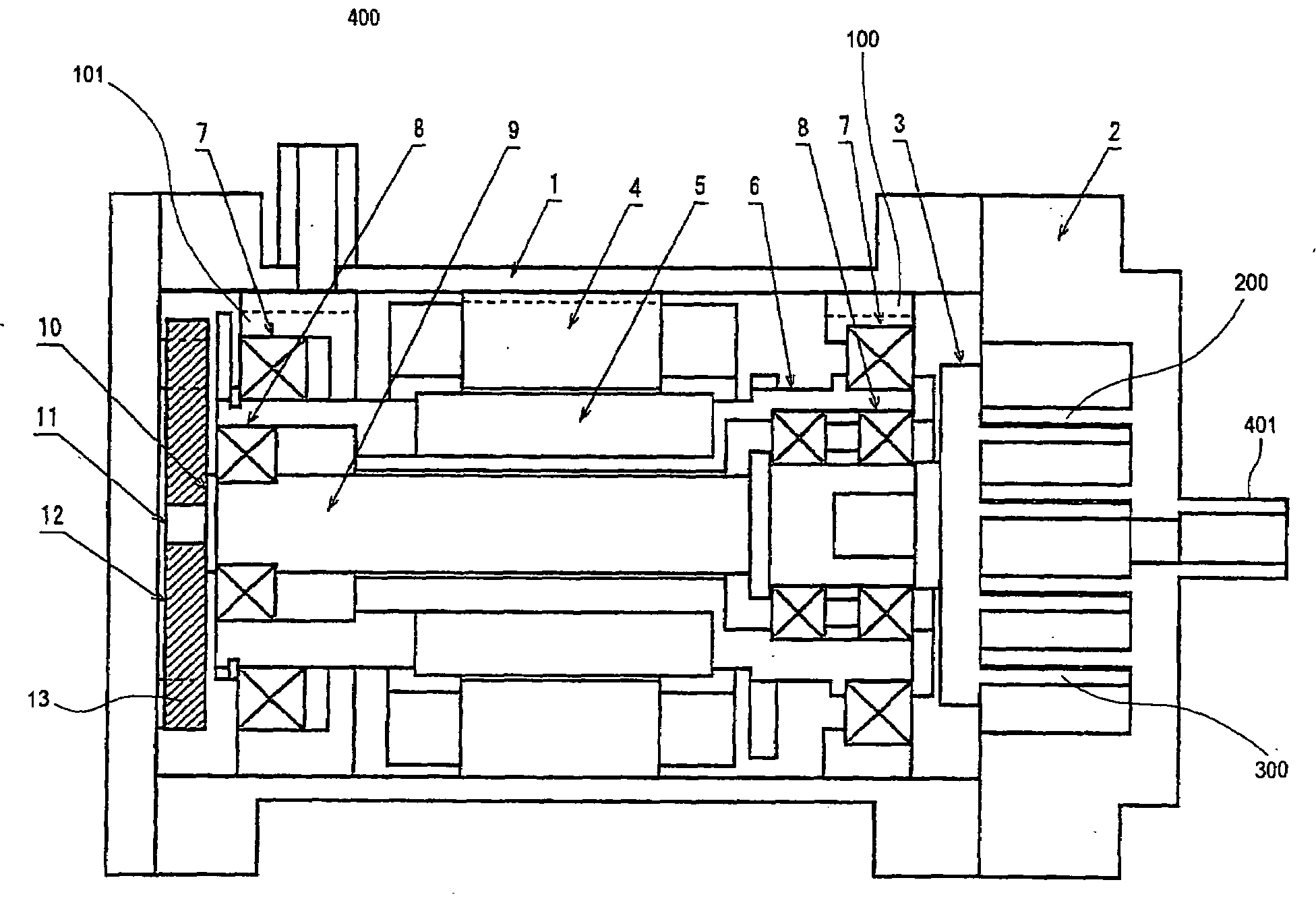
[0022]FIG. 1 is a schematic sectional view showing a scroll fluid machine according to a first embodiment of the invention. A fixed scroll 2 provided with a spiral wrap 200 is fixed to a casing 1. A stator 4 and bearing supports 100, 101 are fixed to the casing 1. A rotary shaft 6 is rotatably supported on the bearing supports 100, 101 via bearings 7. A rotor 5 is fixed to the rotary shaft 6. A motor is formed of the stator 4, the rotor 5 and the like. An eccentric hole having the axis in parallel with that of the rotary shaft 6 is formed to penetrate therethrough. An eccentric shaft (orbiting shaft) 9 is rotatably supported in the eccentric hole of the rotary shaft 6 via bearings 8. The center line of the rotary shaft 6 deviates from that of the eccentric shaft 9. That is, the eccentric shaft 9 is rotatably supported eccentrically with respect to the rotary shaft 6. An orbiting scroll 3 is attached to one end of the eccentric shaft 9. A wrap 300 with the same shape as that of the w...

second embodiment

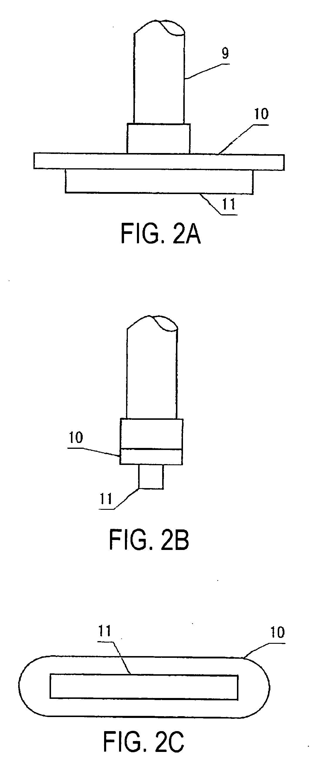
[0033]FIG. 4 shows an orbiting key 11 whose structure is different from that of the first embodiment. FIG. 4A is a front view and FIG. 4B is a bottom view.

[0034]In the embodiment, both end portions 11a of the orbiting key 11 are formed as sliding surfaces. The width of the intermediate portion of the orbiting key 11 is smaller than each width of both end portions. The portion with the reduced width bears no load. The gap between such portion and the long hole 12a of the ring 12 serves to hold the lubricant. Each thickness of both end portions 11a of the orbiting key 11 (not shown) may be increased to be formed as the sliding surface. The intermediate portion of the orbiting key 11 may be made thinner than both end portions.

[0035]The surface of the orbiting plate 10 at the side of the ring 12 is brought into contact with the surface of the ring 12 at the side of the orbiting plate 10. Referring to FIG. 4A, only the end portions 11a of the orbiting key 11 corresponding to the portions...

third embodiment

[0036]FIG. 5 shows a ring 12 whose ring key 12b has different structure from that of the first embodiment. FIG. 5A is a front view and FIG. 5B is a side view.

[0037]In the embodiment, both end portions 12d of the ring key 12b of the ring 12 are made thicker so as to be in contact with the bottom of the key groove 13 as shown in FIG. 5. The other portion of the ring key 12b has the smaller thickness. The structure may suppress the sliding loss and the sliding noise compared with the case where the entire bottom surface of the ring key 12b is in contact with the bottom of the key groove 13.


PUM


Abstract

An anti-self rotation mechanism for preventing self-rotation of the eccentric shaft includes a long orbiting key formed at an end of the eccentric shaft, a ring formed of a long hole through which the orbiting key slides, ring keys that extend toward both outer sides in the direction orthogonal to the longitudinal direction of the hole, and two key grooves formed in the casing, through which the ring keys slide.

Description

PRIORITY[0001]This application claims priority to Japanese Patent Application JP2008-145607, filed Jun. 3, 2008, which is incorporated by reference herein, in its entirety.BACKGROUND OF THE INVENTION[0002]1. Field of the Invention[0003]The invention relates to a scroll fluid machine such as an air compressor, a vacuum pump, a refrigerant gas compressor, a compressor for an oxygen inhaler, and an expander for energy collection and temperature difference power generation.[0004]2. Description of the Related Art[0005]The scroll fluid machine as disclosed in Japanese Patent No. 3540244 includes an eccentric shaft inserted into an eccentric hole formed in a rotary shaft to penetrate therethrough via a bearing, and an anti-self rotation mechanism for preventing self-rotation of the eccentric shaft. The anti-self rotation mechanism for the eccentric shaft includes a frame-like support member fixed to a casing, and a movable plate slidably supported on the support member, which has a long ho...

Claims


Application Information

Patent Timeline
Patent Type & Authority Applications(United States)
IPC IPC(8): F01C1/02
CPCF01C1/0207F04C18/0207F01C21/04F01C17/066F04C18/02F04C29/00
Inventor HWANG, BOOSEOK
Owner RICHSTONE
Why Eureka
Try Eureka