Apparatus for delivery of pressurised gas

a technology for delivering apparatus and gas, which is applied in the field of systems, devices and methods for delivering breathable gases, can solve the problems of large and cumbersome manipulation of devices delivering gases, noisy fans used in devices, and limited number of delivery systems,

Inactive Publication Date: 2009-12-10
COMPUMEDICS MEDICAL INNOVATION
View PDF15 Cites 60 Cited by
  • Summary
  • Abstract
  • Description
  • Claims
  • Application Information

AI Technical Summary

Benefits of technology

[0023]It is an object of the invention to provide a simple humidification system for the pressurised gas. It is a further object of the invention to provide a gas delivery system that is relatively easy to use. It is a further object of the invention to provide a method for delivering humidified gas through a conduit to a subject.
[0024]The invention provides a gas-delivery system that incorporates a humidifier assembly including a removable water reservoir. The invention provides that the humidity level of the gas. passing over the water may be selected by the device user. The invention advantageously incorporates that the controlling variable in setting the humidity level is by adjustment of the temperature of the water in the reservoir, The water reservoir in a gas-delivery device constructed according to the invention can be easily removed for cleaning or replacement.

Problems solved by technology

Prior art gas-delivery systems, methods, and devices generally include a limited number of desirable features.
Similarly, gas may be delivered simply as pressurised air, the unhumidified pressurised air having the potential to cause discomfort by drying out the breathing passages of a patient using the gas for treatment.
A device delivering gases may be large and cumbersome to manipulate.
It is known in the art that fans used in devices can be noisy and cause disturbance to the sleep of patients using the devices.
Such devices are limited in efficacy of controlling flow rate by the speed with which pressure change can be effected by the dynamics of the motor.

Method used


Image

  • Apparatus for delivery of pressurised gas
  • Apparatus for delivery of pressurised gas
  • Apparatus for delivery of pressurised gas

Examples


Embodiment Construction

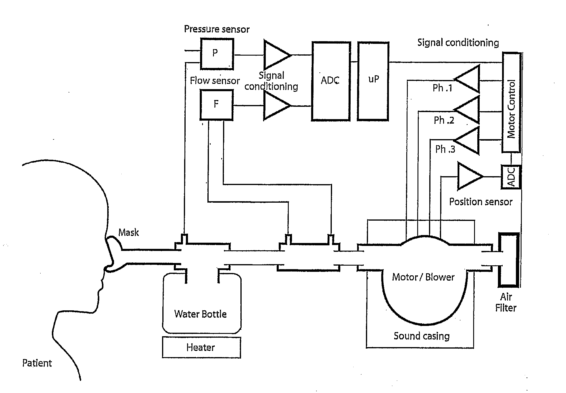
[0041]The invention is most easily understood with reference to the accompanying figures. It will be understood that the figures are intended to be illustrative embodiments of the invention and that the scope of the invention as defined in the claims includes further embodiments not so illustrated. A diagram of representative elements of a pressurised gas-delivery system is shown in FIG. 1. The invention includes that gas is drawn into a gas-delivery device through a replaceable filter system by a motor and blower assembly, the assembly being, encased in a noise-dampening housing to provide quieter operation of the system. A flow-sensing device, located in series with the gas path, may be used to detect the gas flow. Further aspects within the scope of the invention are included in the following description.

Outer Casing

[0042]The following elements are more clearly understood with reference to FIGS. 8 to 14. The outer casing of the gas-delivery device including an upper case 1, a low...


PUM


Abstract

The present invention provides a gas delivery device and system and methods for delivering humidified pressurised gas through a conduit to a subject. The configuration of the elements of the gas delivery device enable the device to be conveniently oriented from a horizontal to vertical position to suit the needs of a user. The gas delivery device may incorporate a Helmholtz resonator for dampening sound of the motor. The conduit may incorporate concentric tubes to allow it to conveniently engage the humidifier at a single aperture. The invention includes a method of operating a blower motor for a gas delivery device using a single Hall sensor.

Description

FIELD OF THE INVENTION[0001]This invention relates to systems, devices and methods for delivering breathable gases. In particular, the invention relates to systems, devices and methods for delivering gases at constant or variable flow rates, pressures, and humidity. More particularly, this invention relates to devices and methods for delivering breathable gases to masks for treatment of breathing disorders.BACKGROUND[0002]There are a number of devices available for the delivery of breathable gas, including air, to a patient for the treatment of disordered breathing, in particular, sleep disordered breathing. For example, in the treatment of sleep apnea, including obstructive sleep apnea, air is often delivered at continuous positive air pressure (CPAP) wherein air is supplied continuously at a pressure greater than ambient to the airway of a sleeping patient through a mask to keep the patient's airway open for effective respiration.[0003]It is important for continuous therapeutic be...

Claims


Application Information

Patent Timeline
Patent Type & Authority Applications(United States)
IPC IPC(8): A61M16/10F04B49/06
CPCA61M16/10A61M16/1075A61M16/16A61M2016/0027A61M16/109A61M2205/42A61M2205/505A61M16/0069A61M2016/0039A61M16/161A61M16/107A61M16/0051A61M16/024A61M16/0816A61M2209/086A61M16/0003A61M16/06
Inventor BURTON, DAVIDBLOCHLINGER, FREDFREEMAN, WARWICKPARRATT, GRANTWALLACE, ALLAN
Owner COMPUMEDICS MEDICAL INNOVATION
Why Eureka
Try Eureka