Plasma processing systems with mechanisms for controlling temperatures of components

a technology of plasma processing and components, applied in the direction of coatings, chemical vapor deposition coatings, electric discharge tubes, etc., can solve the problems of limiting the ultimate parallelism specification that can be achieved, affecting the quality of plasma processing, so as to improve the temperature control of components. , the effect of improving the temperature control

Active Publication Date: 2009-12-10
LAM RES CORP
View PDF8 Cites 9 Cited by
  • Summary
  • Abstract
  • Description
  • Claims
  • Application Information

AI Technical Summary

Benefits of technology

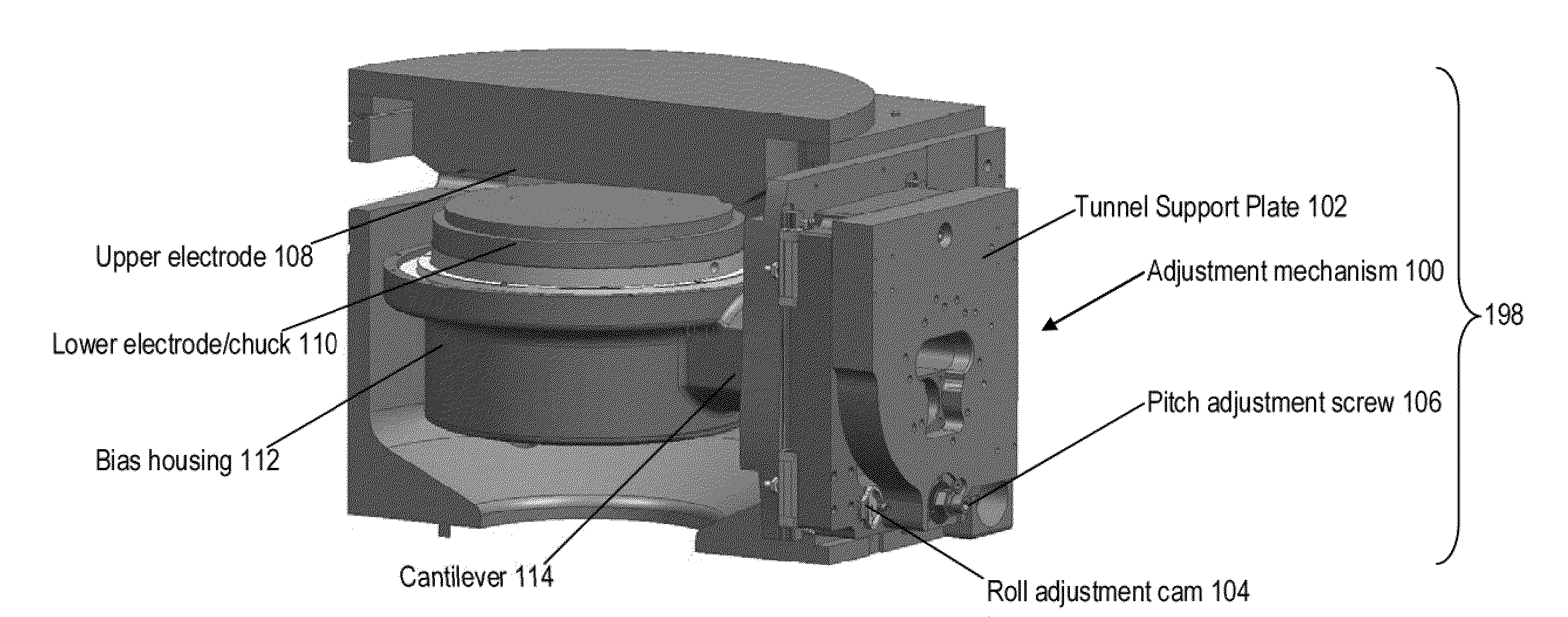
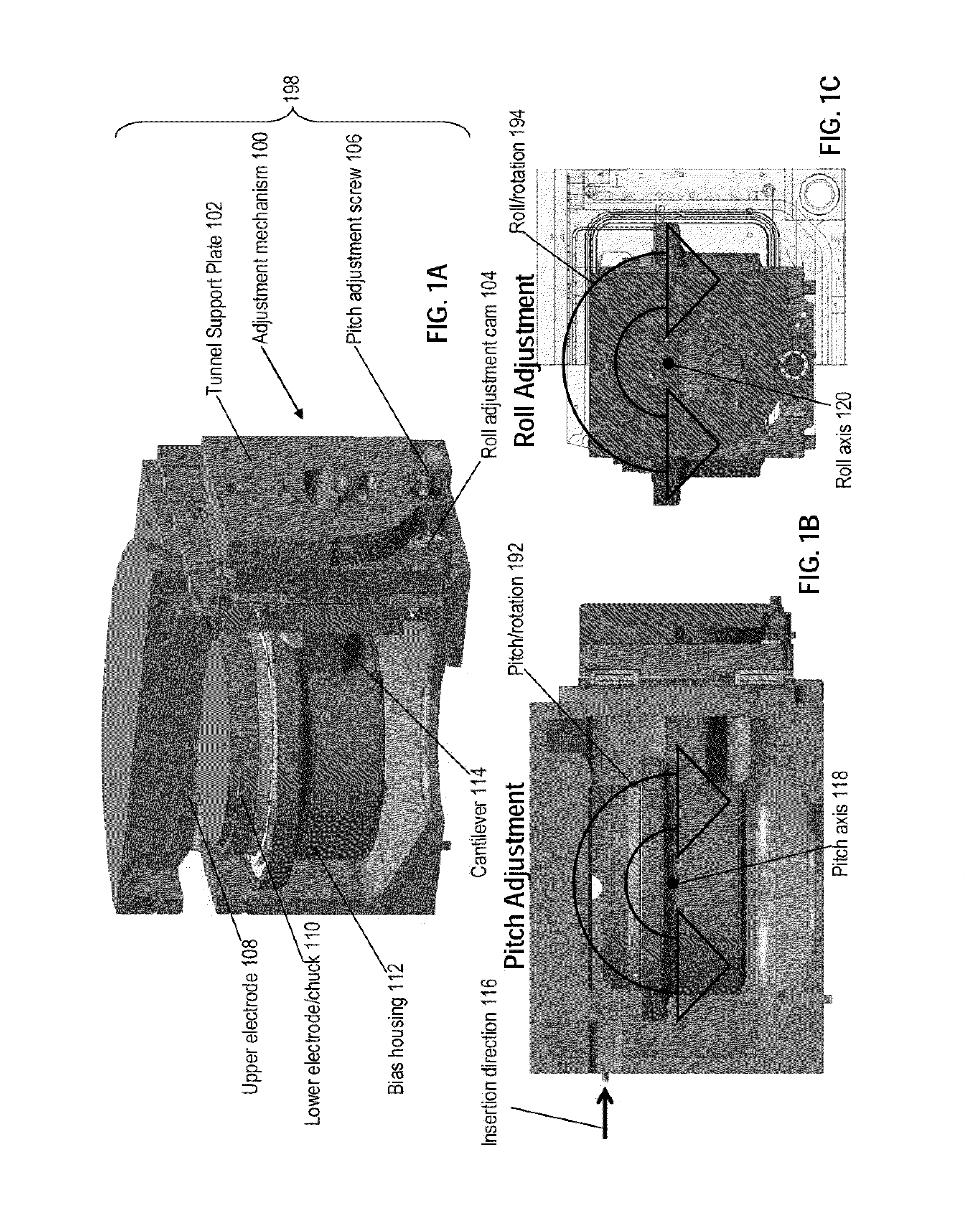
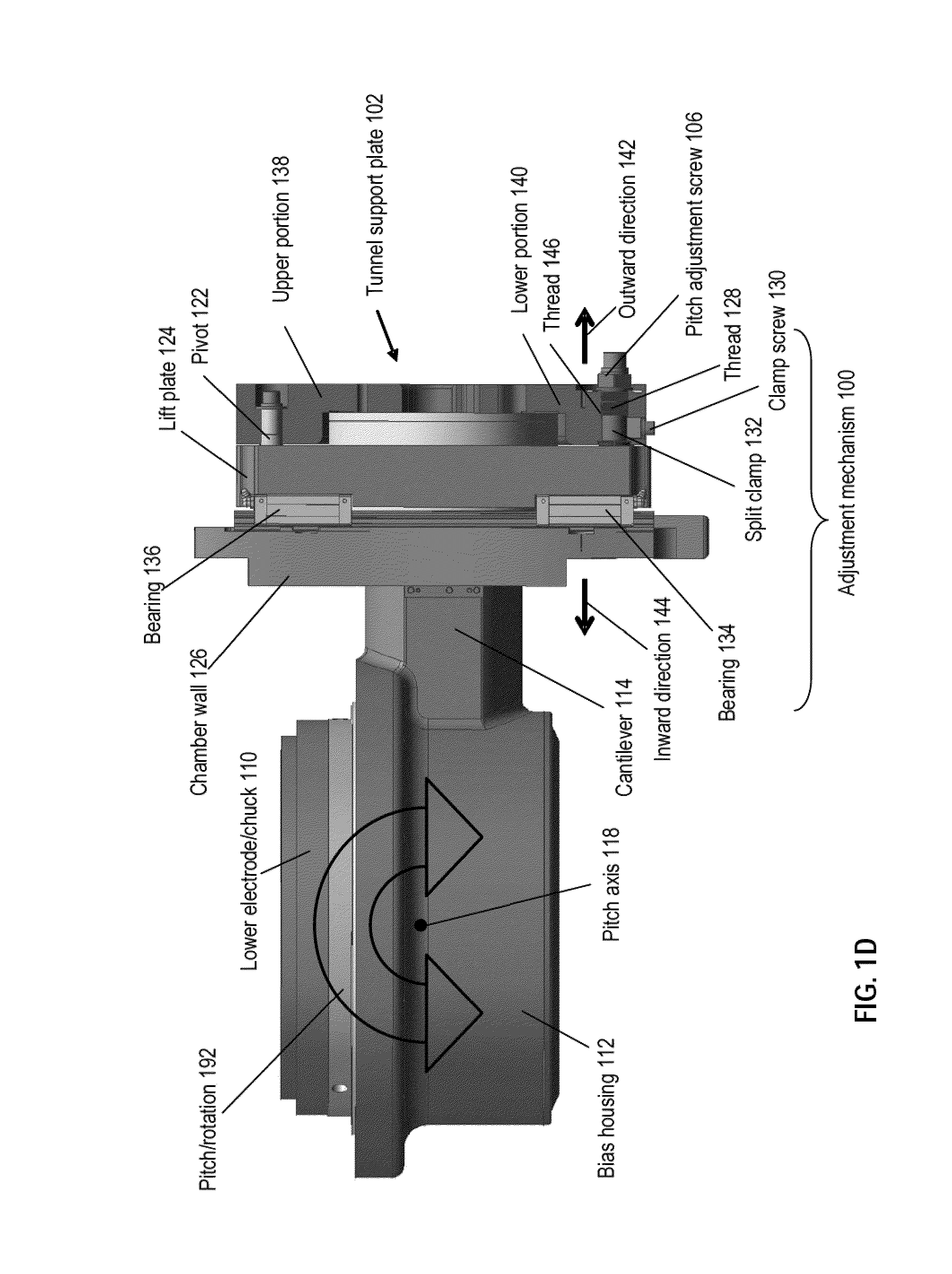
[0008]An embodiment of the present invention relates to a plasma processing system with improved component temperature control. The system may include a plasma processing chamber having a chamber wall. The system may also include an electrode disposed inside the plasma processing chamber. The system may also include a support member disposed inside the plasma processing chamber for supporting the electrode. The system may

Problems solved by technology

The smaller device features, larger substrate size, and new processing techniques (involving multi-step recipes, such as for dual-damascene etch) have increased the challenge to maintain good uniformity across the wafer for better device yields.
Due to added complexity, many capacitively coupled RF plasma reactors may forgo the feature of precise parallelism adjustment between electrodes and may rely on tight manufacturing tolerances of the assembly components to keep parallelism within acceptable limits.
This approach typically adds cost to those components and may limit the ultimate parallelism specification that can be achieved.
For example, given that the assembly components may be subjected to temperature variations and that different components in the reactors may have different thermal

Method used


Image

  • Plasma processing systems with mechanisms for controlling temperatures of components
  • Plasma processing systems with mechanisms for controlling temperatures of components
  • Plasma processing systems with mechanisms for controlling temperatures of components

Examples


Embodiment Construction

[0034]The present invention will now be described in detail with reference to a few embodiments thereof as illustrated in the accompanying drawings. In the following description, numerous specific details are set forth in order to provide a thorough understanding of the present invention. It will be apparent, however, to one skilled in the art, that the present invention may be practiced without some or all of these specific details. In other instances, well known process steps and / or structures have not been described in detail in order to not unnecessarily obscure the present invention.

[0035]One or more embodiments of the invention relate to a plasma processing system with mechanisms for controlling temperatures of components of the plasma processing system. The plasma processing system may include a plasma processing chamber having a chamber wall. Inside the plasma processing chamber, the plasma processing system may include an electrode that may support a substrate during plasma...


PUM

PropertyMeasurementUnit
Diameteraaaaaaaaaa
Surface areaaaaaaaaaaa

Abstract

A plasma processing system with improved component temperature control is disclosed. The system may include a plasma processing chamber having a chamber wall. The system may also include an electrode disposed inside the plasma processing chamber. The system may also include a support member disposed inside the plasma processing chamber for supporting the electrode. The system may also include a support plate disposed outside the chamber wall. The system may also include a cantilever disposed through the chamber wall for coupling the support member with the support plate. The system may also include a lift plate disposed between the chamber wall and the support plate. The system may also include thermally resistive coupling mechanisms for mechanically coupling the lift plate with the support plate.

Description

PRIORITY CLAIM[0001]This application is related to and claims priority under 35 U.S.C. §119(e) to a commonly assigned provisional patent application entitled “Plasma Processing Systems With Mechanisms For Controlling Temperatures of Components,” by James E. Tappan., Attorney Docket Number P1814P / LMRX-P158P1, Application Ser. No. 61 / 060,439 filed on Jun. 10, 2008, all of which are incorporated herein by reference.BACKGROUND OF THE INVENTION[0002]The present invention relates to controlling temperatures of components of plasma processing systems. As an example, the temperature control may relate to components involved in adjusting electrode-to-electrode parallelism in plasma processing systems.[0003]In plasma processing, the shrinking feature sizes and the implementation of new materials in the next generation of device fabrication have put new requirements on plasma processing equipment. The smaller device features, larger substrate size, and new processing techniques (involving mult...

Claims


Application Information

Patent Timeline
IPC IPC(8): B44C1/22C23C16/50
CPCH01J37/32522H01J37/32623H01J37/32568
Inventor TAPPAN, JAMES
Owner LAM RES CORP
Why Eureka
Try Eureka