Overvoltage Protection with Status Signalling

a status signalling and overvoltage protection technology, applied in the direction of resistors, emergency protective arrangements for limiting excess voltage/current, non-adjustable resistors, etc., can solve the problem of increasing the hazard of damage of non-protected electrical equipment, preventing the protective element from properly fulfilling its function, and not identifying

Inactive Publication Date: 2009-12-10
KIWA SPOL
View PDF38 Cites 15 Cited by
  • Summary
  • Abstract
  • Description
  • Claims
  • Application Information

AI Technical Summary

Benefits of technology

[0010]In one embodiment of the present invention, an overvoltage protection device includes at least one non-linear resistance element and a single cut-off device coupled with the at least one non-linear resistance element to disable the at least one non-linear resistance element when the at least one non-linear resistance element reaches a pre-determined temperature. The single cut-off device includes stranded wire, a first solder having a first melting point connecting the stranded wire to the at least one non-linear resistance element, and a second solder having a second melting point, higher than the first melting point, connecting the stranded wire to the at least one non-linear resistance element.
[0011]In particular embodiments, the at least one non-linear resistance element may be a varistor. The single cut-off device may further include a shifting part that shifts when the at least one non-linear resistance element heats the first solder to the first melting point. In addition, the shifting part may shift to disable the at least one non-linear resistance element when the at least one non-linear resistance element heats the second solder to the second melting point. In other particular embodiments, the overvoltage protection device may further include a status indicator configured to be moved by the single cut-off device to indicate one of at least two conditions of the at least one non-linear resistance element. The status indicator may include a lever, and the single cut-off device moves the lever to indicate the one of at least two conditions of the at least one non-linear resistance element.
[0012]An alternate embodiment of the present invention is an overvoltage

Problems solved by technology

Therefore, the overvoltage protection includes a temperature cut-off device which serves to disable the protective element due to its temperature, preventing the protective element from properly fulfilling its function.
The disadvantage of such status indicators is that it does not identify when the overvoltage protection is already partially degraded but not yet disabled from the protected circuit by means of a built in cut-off device.
Due to the fact that only the enabled or disabled status of the protected circuit is indicated, a situation may occur when the overvoltage protection is degraded due to deterio

Method used


Image

  • Overvoltage Protection with Status Signalling
  • Overvoltage Protection with Status Signalling
  • Overvoltage Protection with Status Signalling

Examples


Embodiment Construction

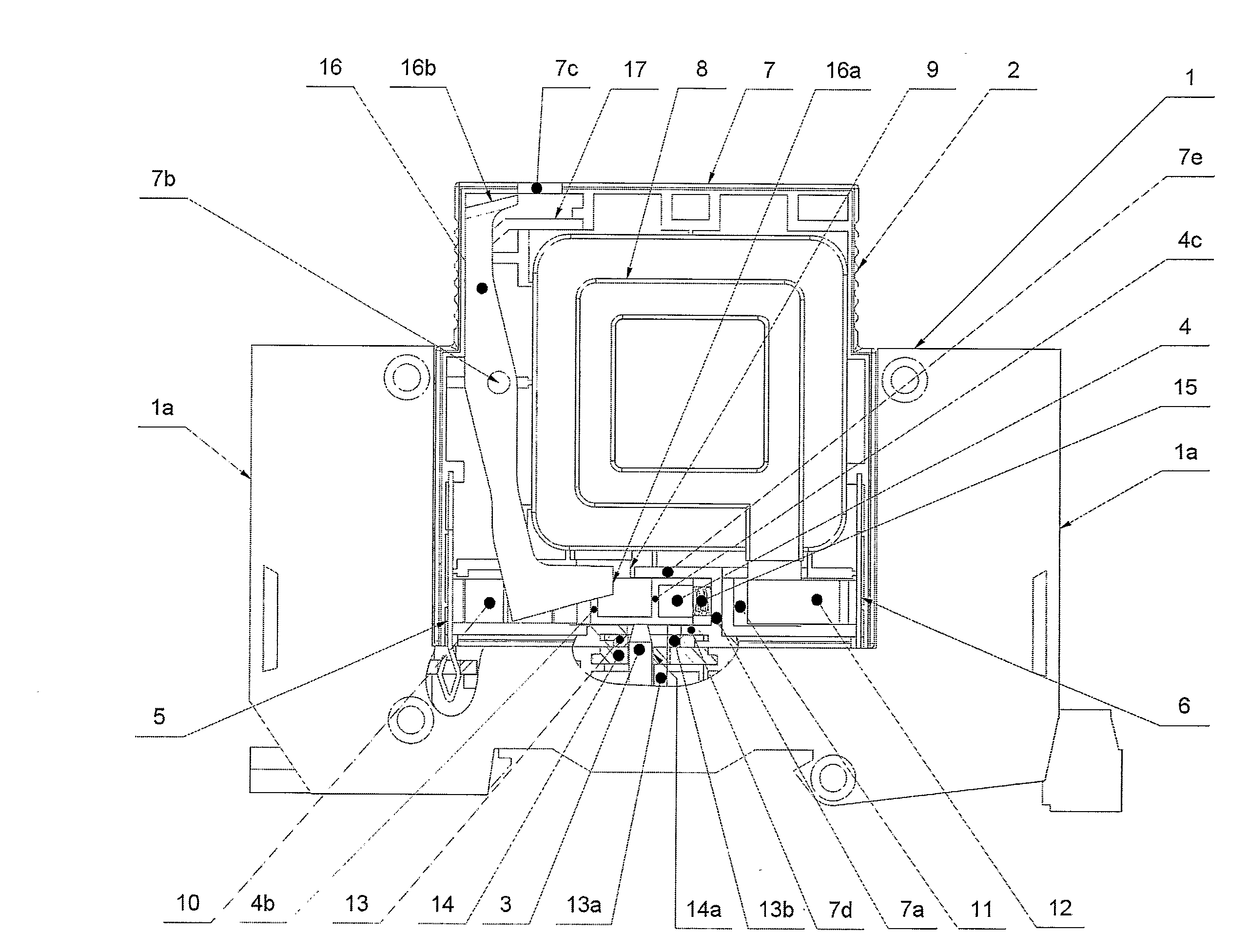
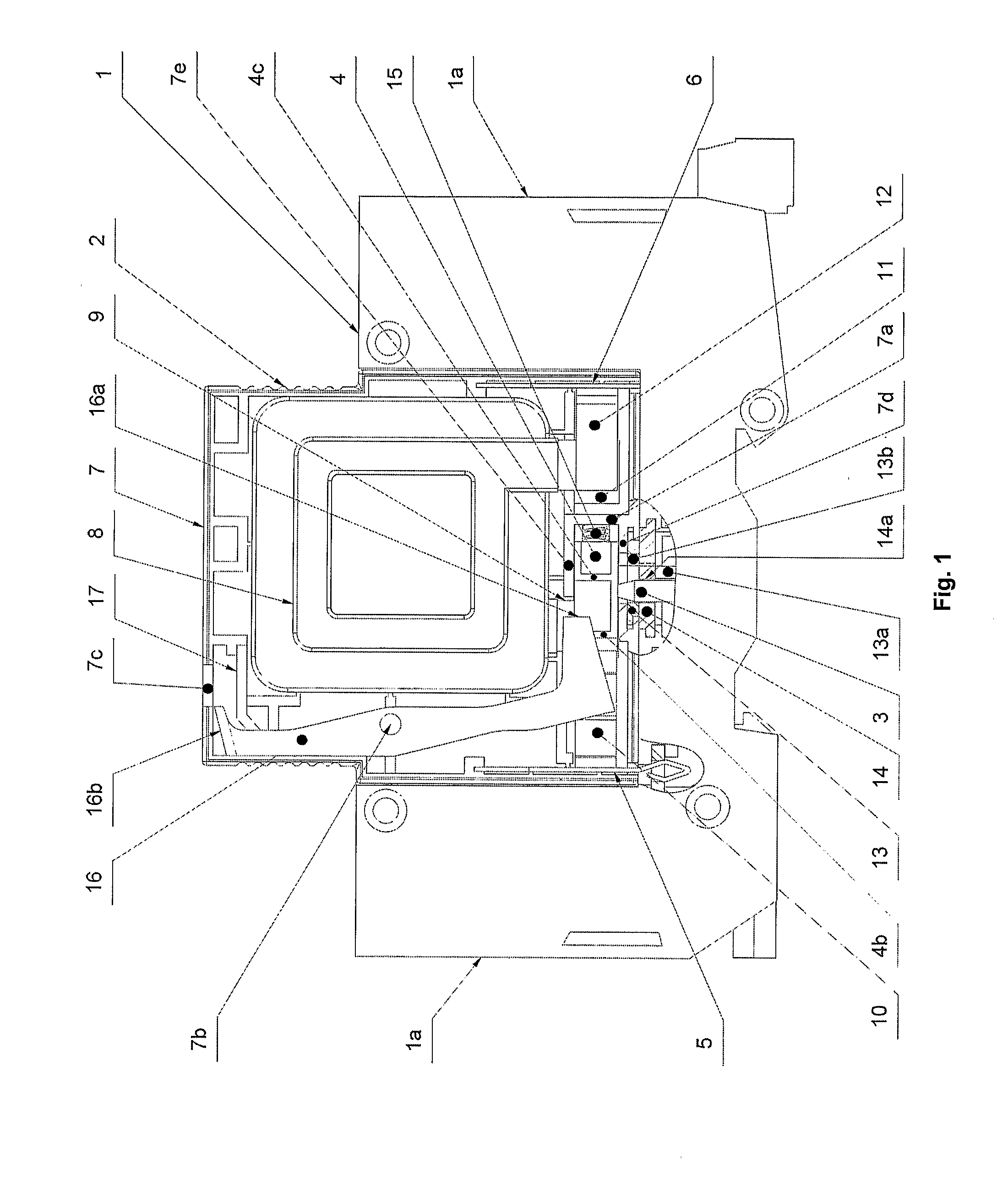
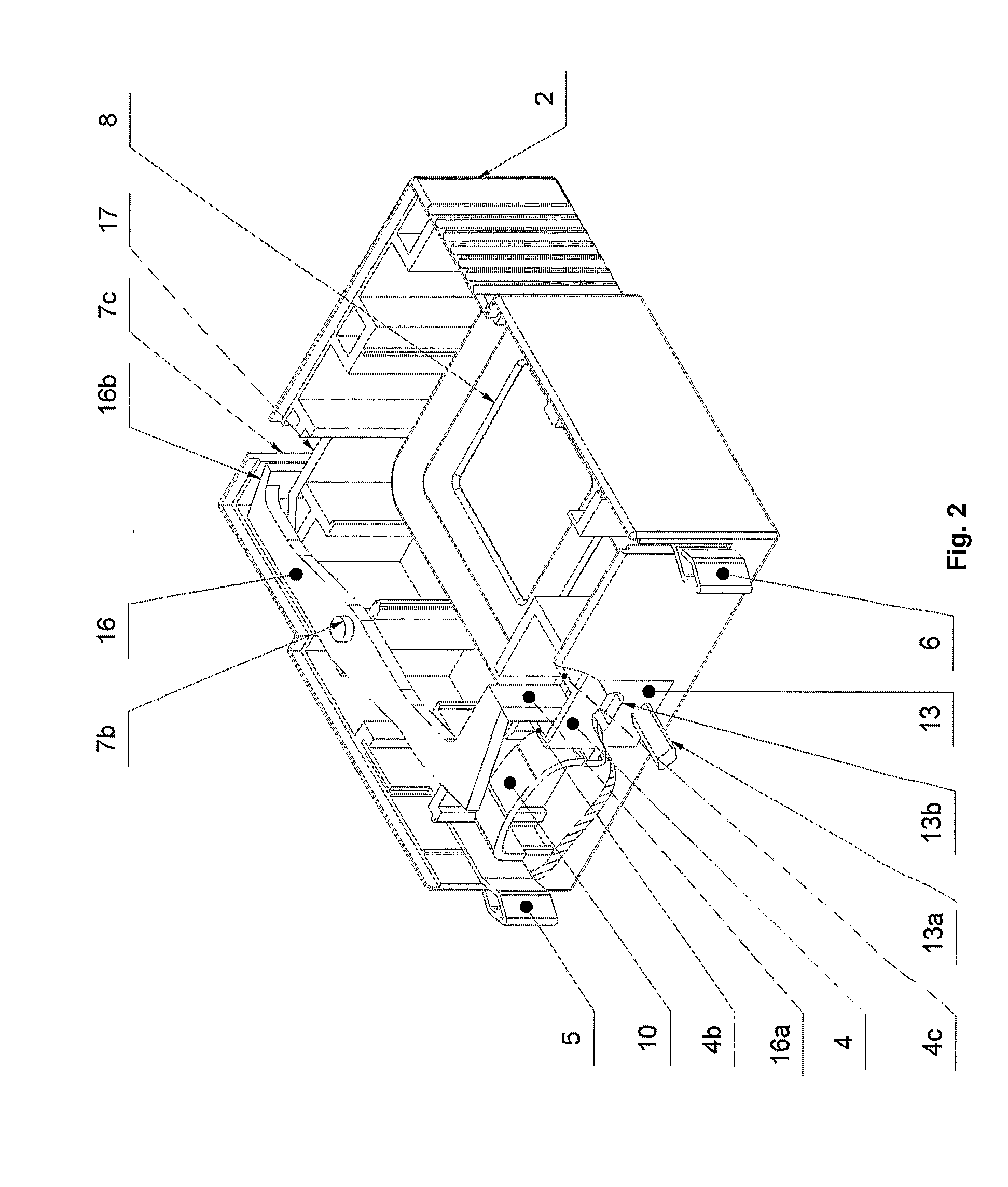
[0041]In one embodiment, an overvoltage protection device may include a holder 1, in which in a replaceable manner a slide-in protective element 2 is mounted. In one holder 1 several slide-in protective elements 2 may be positioned side by side, e.g., for each phase of a three phase electrical line. Also several single pole holders 1 may be connected into one unit, e.g., using rivets. The holder 1 may include arms la and lb that may include clamps (not shown) for connecting electric wires of a protected circuit. In the illustrated embodiment of the overvoltage protection device with remote indication of status change, the holder 1 also includes in its lower part a positioning member 3 of remote indication with a pressure spring (not shown). The holder 1 is provided with means for mechanical and electrical connection of the slide-in protective element 2. For electrical connection between the slide-in protective element 2 and the holder 1, the holder 1 is equipped with current lines a...


PUM


Abstract

The present invention teaches an overvoltage protection device that includes at least one non-linear resistance element and a single cut-off device coupled with the at least one non-linear resistance element to disable the at least one non-linear resistance element when the at least one non-linear resistance element reaches a pre-determined temperature. The single cut-off device may include stranded wire, a first solder having a first melting point connecting the stranded wire to the at least one non-linear resistance element, and a second solder having a second melting point, higher than the first melting point, connecting the stranded wire to the at least one non-linear resistance element. The single cut-off device may further include a shifting part that shifts when the at least one non-linear resistance element heats the first solder to the first melting point. In other particular embodiments, the overvoltage protection device may further include a status indicator configured to be moved by the single cut-off device to indicate one of at least two conditions of the at least one non-linear resistance element. The status indicator may include a lever, and the single cut-off device moves the lever to indicate the one of at least two conditions of the at least one non-linear resistance element.

Description

FIELD OF THE INVENTION[0001]The invention relates to an overvoltage protection device having at least one non-linear resistance element with a cut-off device coupled with a status indicator of overvoltage protection.BACKGROUND[0002]Overvoltage protection devices have a protective element which generally includes a non-linear element (varistor) which, due to its loading of electric current and by an impulse loading of a protected network, gradually decreases the value of its resistance. Due to this, the current running through the protective element increases, and its temperature increases as well. Therefore, the overvoltage protection includes a temperature cut-off device which serves to disable the protective element due to its temperature, preventing the protective element from properly fulfilling its function. Disabling the protective element from the network is indicated either visually directly on the overvoltage protection or remotely by transmission of a suitable signal. Once...

Claims


Application Information

Patent Timeline
IPC IPC(8): H01H37/76
CPCH01C7/126
Inventor CERNICKA, JOZEF
Owner KIWA SPOL
Why Eureka
Try Eureka