Direct current circuit breaker and method using the same

a circuit breaker and direct current technology, applied in the direction of electronic switching, emergency protective arrangements for limiting excess voltage/current, pulse technique, etc., can solve the problems of large electrical current loss, inadvertent hvdc transmission, electrical current loss, etc., to reduce manufacturing costs, small size, and large breaking capacity

Inactive Publication Date: 2016-04-14
LSIS CO LTD
View PDF9 Cites 15 Cited by
  • Summary
  • Abstract
  • Description
  • Claims
  • Application Information

AI Technical Summary

Benefits of technology

[0027]With the DC circuit breaker according to the aspect of the present disclosure, manufacturing cost can be reduced by configuring the circuit breaker to include a high-speed switch and a plurality of pairs of a non-linear resistor and a current-limiting power fuse for the purpose of breaking the fault-current.
[0028]Further, since the current-limiting power fuse has an advantage in that it has a small size but a large breaking capacity, the DC circuit breaker can be made smaller and lighter and easily maintained.
[0029]In the method using the DC circuit breaker according to the another aspect of the present disclosure, the DC circuit breaker may be operated in two different modes: a rated current interruption mode for the purpose of the maintenance and replacement of a device and a fault-current interruption mode when a fault occurs in a line. Therefore, it is possible to avoid replacing a current-limiting power fuse, which frequently occurs in the system when the system is interrupted. As a result, the maintenance cost can be further reduced.

Problems solved by technology

Unfortunately, such a DC circuit breaker employing power semiconductor switches suffers a large electrical current loss, and thus is not appropriate for HVDC transmission.
In addition, such a large number of power semiconductor switches result in electrical current loss.
Since the power semiconductor switches are expensive, manufacturing cost of the DC circuit breaker increase.

Method used


Image

  • Direct current circuit breaker and method using the same
  • Direct current circuit breaker and method using the same
  • Direct current circuit breaker and method using the same

Examples


Embodiment Construction

[0036]Hereinafter, preferred exemplary embodiments of the present disclosure will be described with reference to accompanying drawings. The present disclosure will be described in detail to enable those skilled in the art to easily practice the present disclosure. However, the technical idea and scope of the present disclosure is not limited thereto.

[0037]DC circuit breakers according to embodiments of the present disclosure will be described in detail with reference to the drawings.

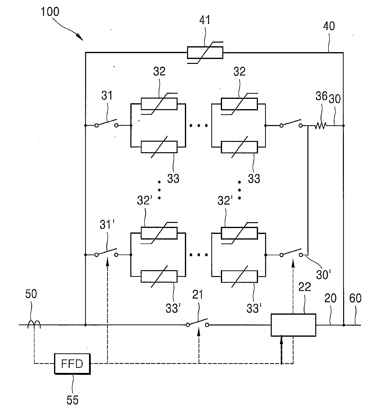
[0038]FIG. 3 is a block diagram of a DC circuit breaker according to an embodiment of the present disclosure.

[0039]Referring to FIG. 3, the DC circuit breaker includes: a first line 20 in which a high-speed switch 21 and a power semiconductor switch 22 are connected in series; a second line 30 in which a high-speed switches 31, a plurality of pairs of a non-linear resistor 32 and a power fuse 33 connected in parallel, and a resistor 36 are connected in series; and a third line 40 including a non-linear r...


PUM

PropertyMeasurementUnit
speedaaaaaaaaaa
voltage capacityaaaaaaaaaa
currentaaaaaaaaaa

Abstract

Disclosed is a direct current (DC) circuit breaker including a first line in which a first high-speed switch and a power semiconductor switch are connected in series; a second line in which a plurality of second high-speed switches, a plurality of pairs of a first non-linear resistor and a power fuse connected in parallel, and a resistor are connected in series; and a third line including a second non-linear resistor. The first line, the second line, and the third line are connected in parallel.

Description

CROSS REFERENCE TO RELATED APPLICATION[0001]This application claims the benefit of Korean Patent Application No. 10-2014-0136914, filed on Oct. 10, 2014, entitled “DIRECT CURRENT CIRCUIT BREAKER AND METHOD USING THE SAME”, which is hereby incorporated by reference in its entirety into this applicationBACKGROUND[0002]1. Technical Field[0003]The present disclosure relates to a direct current (DC) circuit breaker and a method using the same. More specifically, the present disclosure relates to a DC circuit breaker for quickly and efficiently interrupting a high-voltage direct-current (HVDC) system for protecting devices as well as the system at the time of maintenance or replacement of a device, or when a fault-current occurs in a transmission line or a distribution line of the system. The present disclosure also relates to a method using the same.[0004]2. Description of the Related Art[0005]In general, a DC circuit breaker is used for quickly and efficiently interrupting a high-voltag...

Claims


Application Information

Patent Timeline
Patent Type & Authority Applications(United States)
IPC IPC(8): H02H3/087
CPCH02H3/087H03K17/567H03K17/687H01H9/541H01H33/596H01H2009/543H02H3/00
Inventor LEE, GYEONG-HOSIM, JUNG-WOOKPARK, HAE-YONG
Owner LSIS CO LTD
Why Eureka
Try Eureka