
Direct Current Switch-Off Device And Control Method Thereof

a technology of switch-off device and control method, which is applied in the direction of high-tension/heavy-dress switch, circuit arrangement, electrical apparatus, etc., can solve the problems of poor economic benefits, high cost of direct current breaker, and inability to meet the requirements of multi-terminal flexible direct current transmission system in terms of breaking time and current breaking capability, etc., to improve the breaking speed of the switch, prolong the service life of the switch, and reduce the loss of the on-state

Active Publication Date: 2019-01-17
NR ELECTRIC CO LTD +1
View PDF7 Cites 14 Cited by
  • Summary
  • Abstract
  • Description
  • Claims
  • Application Information

AI Technical Summary

Benefits of technology

The present invention is providing a direct current switch-off device that solves the problem of high cost and low efficiency in prior art. The device has a high breaking speed and low loss, and also has a reclosing function to reduce line voltage fluctuation. The device has a reduced number of fully-controlled devices, which leads to reduced equipment cost. The device uses a mechanical switch and power electronics to ensure low on-state loss and a long service life for the switch. Overall, the present invention offers a cost-effective and efficient solution for direct current switch-off applications.

Problems solved by technology

The mechanical breaker fabricated according to this principle cannot meet the requirements of a multi-terminal flexible direct current transmission system in terms of breaking time and current-breaking capability.
Although the solid-state breaker fabricated according to this principle can meet the requirements of a multi-terminal flexible direct current system in terms of time, an excessive loss occurs when the breaker is normally conducting current, resulting in poor economic benefits.
However, to cut off line currents in two directions, a large number of fully-controlled devices need to be forwardly connected in series and then reversely connected in series.
Due to the large quantity and high price of the fully-controlled devices, the direct current breaker is expensive, and the wide application and promotion of the direct current breaker are affected.
The reclosing of a direct current line may easily cause line voltage fluctuation, and the amplitude reaches double of a normal direct current voltage, which affects the safe and reliable operation of the system, so that a pre-charge operation needs to be performed on the faulty line first.
“201510661262.7” entitled “HIGH-VOLTAGE DIRECT CURRENT BREAKER AND CONTROL METHOD THEREOF”, although a reclosing operation can be performed, a large switching overvoltage is produced as a pre-charge process is not performed on the line during the reclosing operation, which has a negative effect on safe operation of the device.

Method used


Image

  • Direct Current Switch-Off Device And Control Method Thereof
  • Direct Current Switch-Off Device And Control Method Thereof
  • Direct Current Switch-Off Device And Control Method Thereof

Examples


first embodiment

of the Buffering and Reclosing Module

[0076]As shown in FIG. 10, the buffering and reclosing circuit includes a capacitor, a resistor, and a reclosing module which are connected in parallel. The reclosing module includes a resistor and a fully-controlled device which are connected in series.

second embodiment

of the Buffering and Reclosing Module

[0077]As shown in FIG. 11, the buffering and reclosing circuit includes a capacitor, a resistor, and a reclosing module which are connected in parallel. The reclosing module includes a resistor, a fully-controlled device, and an uncontrolled device. The resistor and the fully-controlled device are connected in series. The uncontrolled device is connected in parallel on two ends of the resistor. The fully-controlled device and the uncontrolled device are connected in series in opposite directions.

third embodiment

of the Buffering and Reclosing Module

[0078]As shown in FIG. 12, the buffering and reclosing circuit includes an RCD module and a reclosing module. The RCD module includes an uncontrolled device, a capacitor, and two resistors. The uncontrolled device and the capacitor are connected in series, a cathode of the uncontrolled device is connected to one end of the capacitor, and the two resistors are connected in parallel on two ends of the uncontrolled device and on two ends of the capacitor respectively. The reclosing module includes a resistor and a fully-controlled device which are connected in series. The reclosing module and the RCD module are connected in parallel.


PUM


Abstract

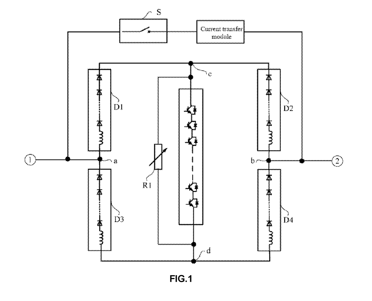
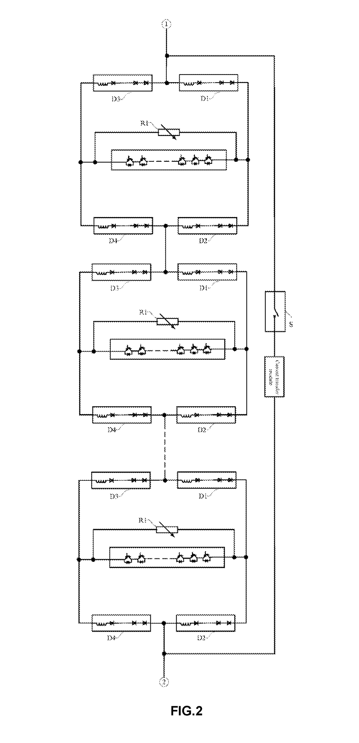
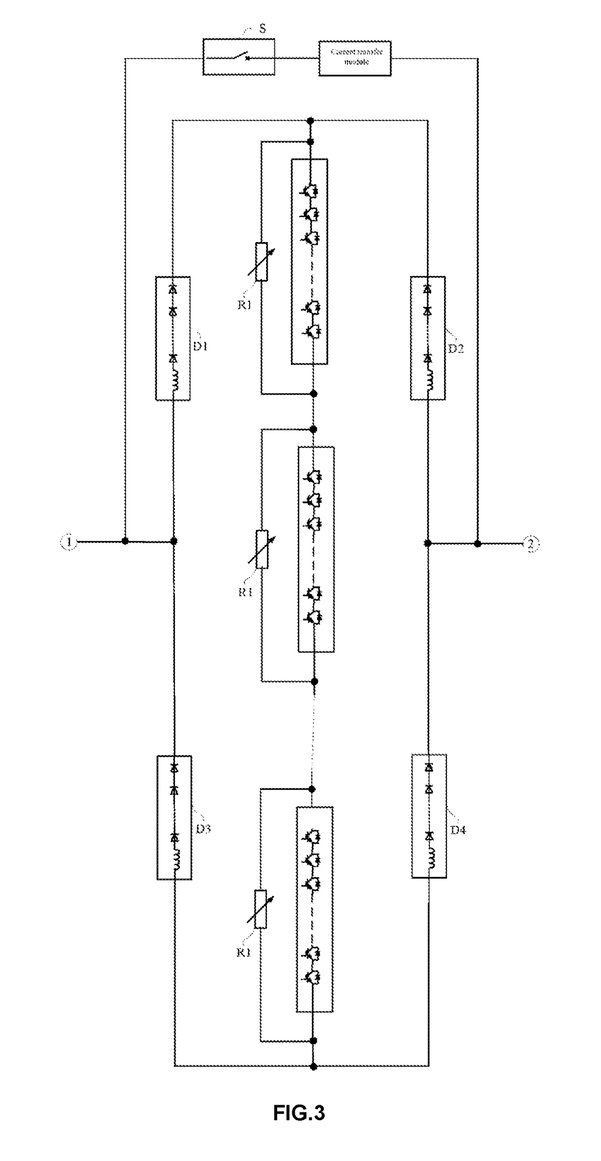
A direct current switch-off device comprises an on-state current branch circuit and a current commutating and breaking unit which are connected in parallel. The on-state current branch circuit has a mechanical switch (S) and a current transfer module which are connected in series. The current commutating and breaking unit comprises a bridge-type branch circuit and a current-breaking branch circuit. The current-breaking branch circuit and two bridge arms of the bridge-type branch circuit are connected in parallel. The current-breaking branch circuit comprises a nonlinear resistor (RI) and a valve group consisting of fully-controlled devices connected in series. The nonlinear resistor (RI) and the valve group are connected in parallel. Two ends of each fully-controlled device in the valve group are connected in parallel with a buffering and reclosing circuit.

Description

BACKGROUND OF THE INVENTIONTechnical Field[0001]The present invention relates to a direct current switch-off device and also to a control method of the direct current switch-off device, which belong to the technical field of direct current breakers.Background Art[0002]With the development of multi-terminal direct current transmission technologies, a direct current breaker will become one of the key devices that ensure safe and stable operation of the power system. Since a multi-terminal high-voltage direct current transmission system has a high voltage level and small line impedance, once a short-circuit failure occurs in a line, both the direct current grid and the alternating current grid will be influenced soon, so that the failure needs to be cleared in time. Therefore, the direct current breaker should act quickly to reduce the duration of the failure or limit the fault current to the maximum extent, thus lowering the impact of the failure on the alternating current / direct curr...

Claims


Application Information

Patent Timeline
Patent Type & Authority Applications(United States)
IPC IPC(8): H02H7/26H01H9/54
CPCH02H7/268H01H2009/543H01H2009/544H01H9/542H01H33/596H02H3/087H02H3/06H02H7/26
Inventor CAO, DONGMINGFANG, TAIXUNXIE, YEYUANYANG, BINGSHI, WEILV, WEIWANG, WENJIELIU, BINWANG, TAOLI, LELE
Owner NR ELECTRIC CO LTD
Learn More