Omnidirectional RFID antenna

a technology of omnidirectional antennas and antennas, applied in the direction of polarised antenna unit combinations, instruments, burglar alarm mechanical actuation, etc., can solve the problems of not being able to communicate between the two, not being able to parasitically power the tag, and not being able to optimally transfer the energy from the reader to the integrated circui

Active Publication Date: 2009-12-10
RADIOFIDO
View PDF12 Cites 20 Cited by
  • Summary
  • Abstract
  • Description
  • Claims
  • Application Information

AI Technical Summary

Benefits of technology

[0009]In order to make a tag having an orientation-independent response relative to the reader, the antenna for the tag is designed to have a circular polarization. If the reader also has a dual circularly polarized antenna, then a maximum amount of power i

Problems solved by technology

Since the linear polarization makes the tag directional, this presents problems when transmitting from the reader to the tag and vice versa.
It will be appreciated that the orientation of the tag is not known, which means that there will not be optimal efficiency in transfer

Method used


Image

  • Omnidirectional RFID antenna
  • Omnidirectional RFID antenna
  • Omnidirectional RFID antenna

Examples


Embodiment Construction

[0040]What is now presented is a description of antenna polarization and the effects of polarization mismatch loss.

Antenna Polarization

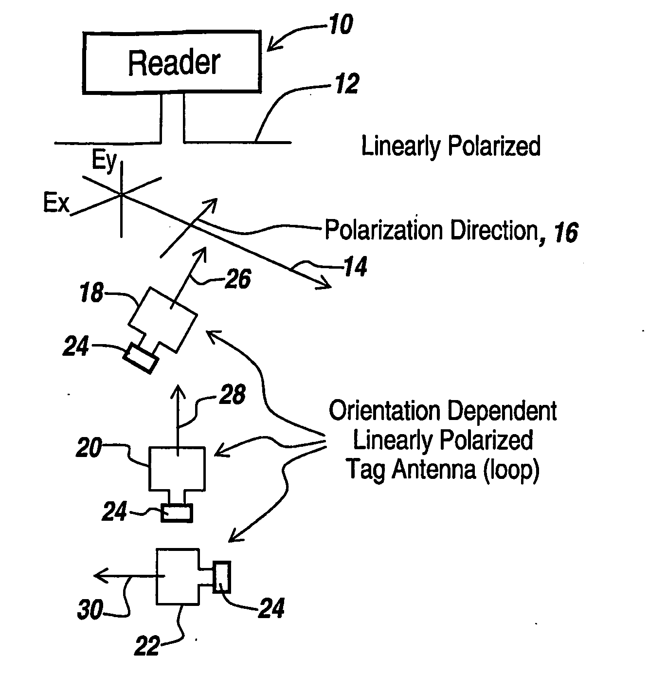
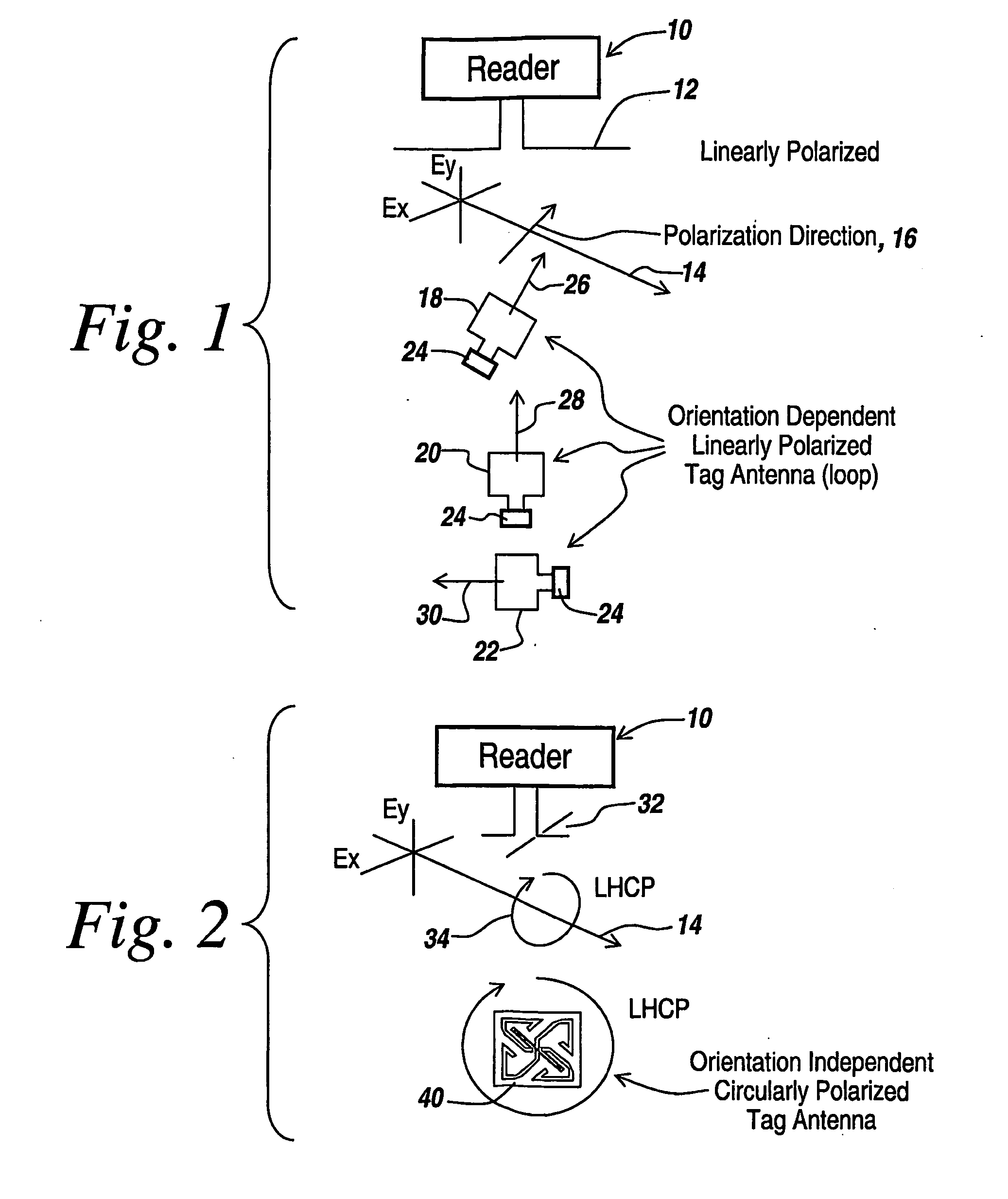
[0041]The energy radiated by any antenna is contained in a transverse electromagnetic wave that is comprised of an electric and a magnetic field. These fields are always orthogonal to one another and orthogonal to the direction of propagation. The electric field of the electromagnetic wave is used to describe its polarization and hence, the polarization of the antenna.

[0042]In general, all electromagnetic waves are elliptically polarized. In this general case, the total electric field of the wave is comprised of two linear components, which are orthogonal to one another. Each of these components has a different magnitude and phase. At any fixed point along the direction of propagation, the total electric field would trace out an ellipse as a function of time. At any instant in time, Ex is the component of the electric field in the x-direction and Ey ...


PUM


Abstract

Antennas (50) for RFID tags are made to exhibit circular polarization to give the tag an omnidirectional characteristic. The antennas are crossed dipoles (52,54) with respective feed points (56,58). The signal source (60) is coupled to a splitter (62) having output leads (64) directly coupled to the feed point (56) of dipole (52). The other output leads (66) from splitter (62) are coupled to a delay line (68) with the delayed output coupled to a feed point (58) of dipole (54).

Description

RELATED APPLICATIONS[0001]This application claims rights under 35 USC § 119(e) from U.S. application Ser. No. 60 / 726,146 filed Oct. 13, 2005, the contents of which are incorporated herein by reference. This application is related to three U.S. applications: U.S. Application Serial No. US2006 / 033111 filed Aug. 24, 2006 by Kenneth R. Erikson of Henniker, N.H., entitled “RFID Tag and Method and Apparatus for Manufacturing Same;” U.S. Application Serial No. US2006 / 033048 filed Aug. 24, 2006 by Court Rossman of Merrimack, N.H., Zane Lo of Merrimack, N.H., Roland Gilbert of Milford, N.H. and John Windyka of Amherst, N.H., entitled “Methods for Coupling an RFID Chip to an Antenna;” and U.S. Provisional Application No. 60 / 726,145, filed Oct. 13, 2005 by Karl D. Brommer of Exeter, N.H. and Kenneth R. Erikson of Henniker, N.H., entitled “RFID Tag Incorporating at Least Two Integrated Circuits.” The contents of these three applications are incorporated herein by reference.FIELD OF THE INVENTIO...

Claims


Application Information

Patent Timeline
IPC IPC(8): H04Q5/22
CPCH01Q21/26H01Q1/2208
Inventor ROSSMAN, COURT E.LO, ZANE
Owner RADIOFIDO
Why Eureka
Try Eureka