Multiband Omnidirectional Antenna

a multi-band omni-directional antenna and antenna technology, applied in the direction of antennas, antenna details, antenna adaptation in movable bodies, etc., can solve the problem of general over-cost of amplifiers for impedance adjustmen

Active Publication Date: 2009-12-10
ROBERT BOSCH GMBH
View PDF8 Cites 5 Cited by
  • Summary
  • Abstract
  • Description
  • Claims
  • Application Information

AI Technical Summary

Benefits of technology

[0013]In particular, at least one of the connecting elements may have an electronic component to make it possible to exactly adjust the impedances of the multiband omnidirectional antenna.

Problems solved by technology

If possible, the antenna structures should not protrude from the vehicle body, because they could interfere with the design of the vehicle shell.
However, for cellular radio systems, for example, the use of an amplifier for impedance adjustment is generally too expensive; that is why the antenna structures were previously provided with suitable impedances which, however, for lack of space had to be installed in such a way that they protruded beyond the vehicle shell.

Method used


Image

  • Multiband Omnidirectional Antenna
  • Multiband Omnidirectional Antenna
  • Multiband Omnidirectional Antenna

Examples


Embodiment Construction

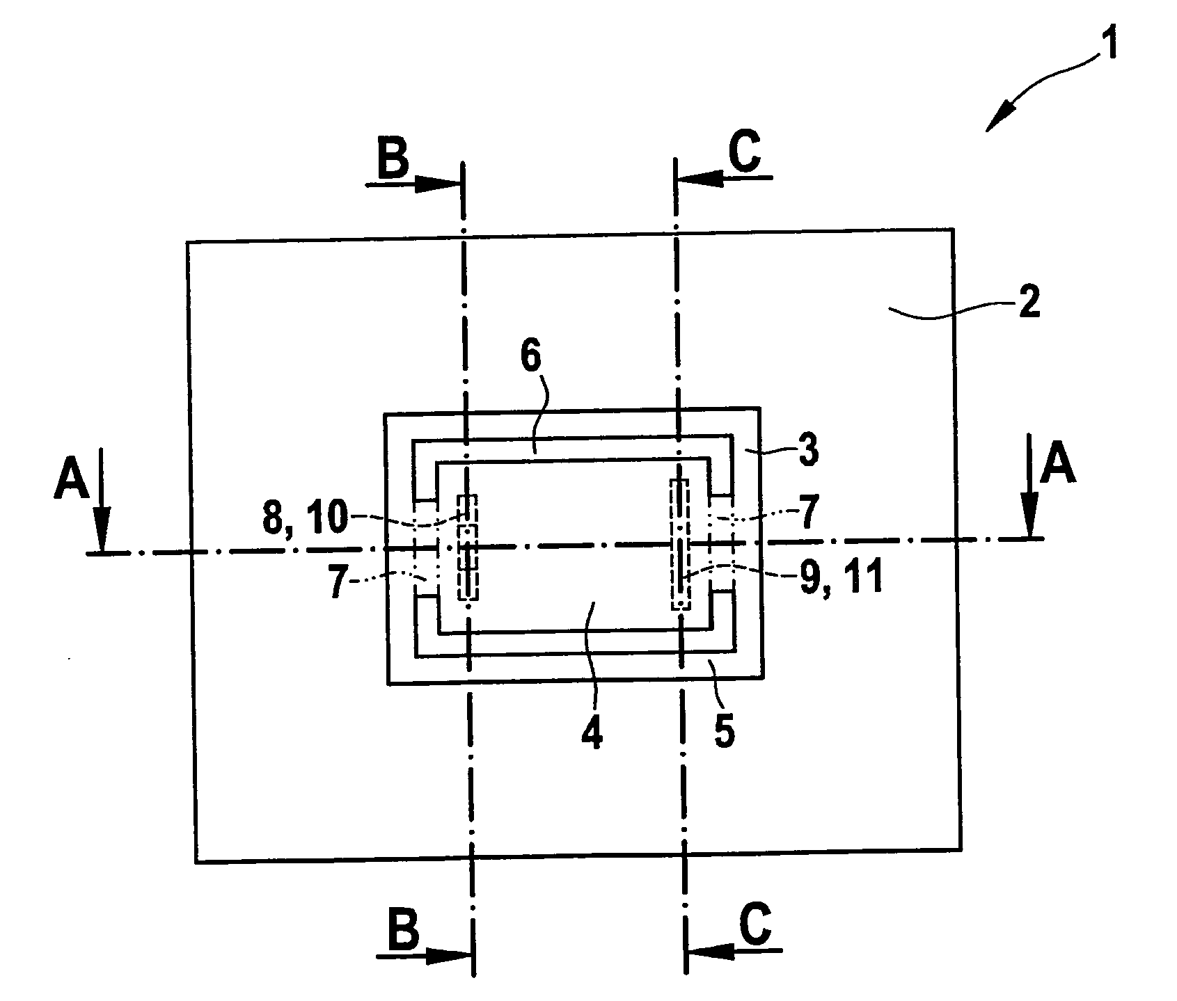
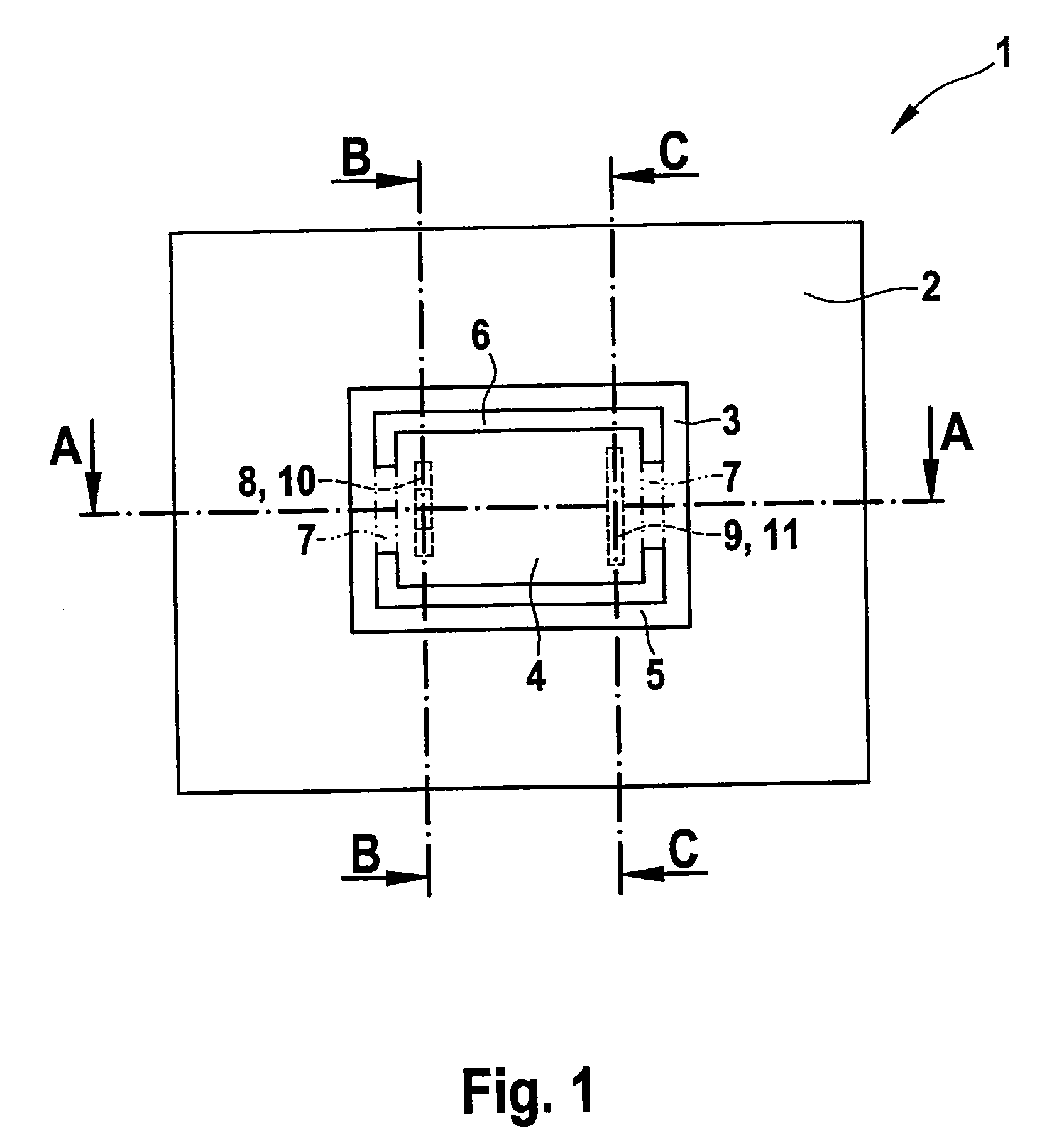
[0023]FIG. 1 shows a top view onto a multiband omnidirectional antenna 1 according to an exemplary embodiment of the present invention. Multiband omnidirectional antenna 1 has a grounded face 2 which has a conductive, in particular metallic, surface. A planar antenna element 3, which is also made of a conductive material and has a conductive surface, is situated essentially plane-parallel at a certain first distance above the surface of grounded face 2. Antenna element 3 may be manufactured as a stamped part in particular.

[0024]Planar antenna element 3 has a first planar emitter 4 which has an essentially square, which may be a rectangle, shape. First planar emitter 4 is surrounded by a second planar emitter 5 whose outer edges also form a rectangle. Second planar emitter 5 surrounds the first planar emitter which may be at a predefined second distance so that a slot 6 is formed between first planar emitter 4 and second planar emitter 5. First planar emitter 4 and second planar emit...


PUM


Abstract

A multiband omnidirectional antenna which includes a grounded face and an antenna element situated parallel to the grounded face, the antenna element having a first planar emitter, which has a planar design and extends parallel to the grounded face, a second planar emitter, which surrounds the first planar emitter at a distance, and at least two connection elements for connecting the first and the second planar emitters to each other.

Description

FIELD OF THE INVENTION[0001]The present invention relates to a multiband omnidirectional antenna, in particular for installation in a vehicle body.BACKGROUND INFORMATION[0002]Modern vehicles are increasingly equipped with radio and communication devices which need suitable antenna structures for transmitting and receiving radio signals. If possible, the antenna structures should not protrude from the vehicle body, because they could interfere with the design of the vehicle shell. For this reason it is desirable to install antenna structures into the body in such a way that they do not protrude beyond the vehicle shell. This is known already for reception systems such as radio and TV reception systems which to some extent use multiple antennas to obtain a desired omnidirectional reception. Moreover, amplifiers are used in order to be able to keep the losses, caused by the maladjustment to typical antenna cables, low or even equalize them.[0003]However, for cellular radio systems, for...

Claims


Application Information

Patent Timeline
Patent Type & Authority Applications(United States)
IPC IPC(8): H01Q1/38H01Q5/00H01Q5/321H01Q5/357
CPCH01Q1/3275H01Q9/0421H01Q5/357H01Q5/321H01Q9/0442
Inventor SCHANO, THOMAS
Owner ROBERT BOSCH GMBH
Why Eureka
Try Eureka