Front end circuit and wireless communication device
a wireless communication device and front end technology, applied in the field of front end circuits and wireless communication devices, can solve the problems of difficult to widen the range over which the impedance can be adjusted, the control system is not easy to operate, and the circuit scale of the antenna circuit is complicated, so as to achieve the effect of increasing isolation
- Summary
- Abstract
- Description
- Claims
- Application Information
AI Technical Summary
Benefits of technology
Problems solved by technology
Method used
Image
Examples
first embodiment
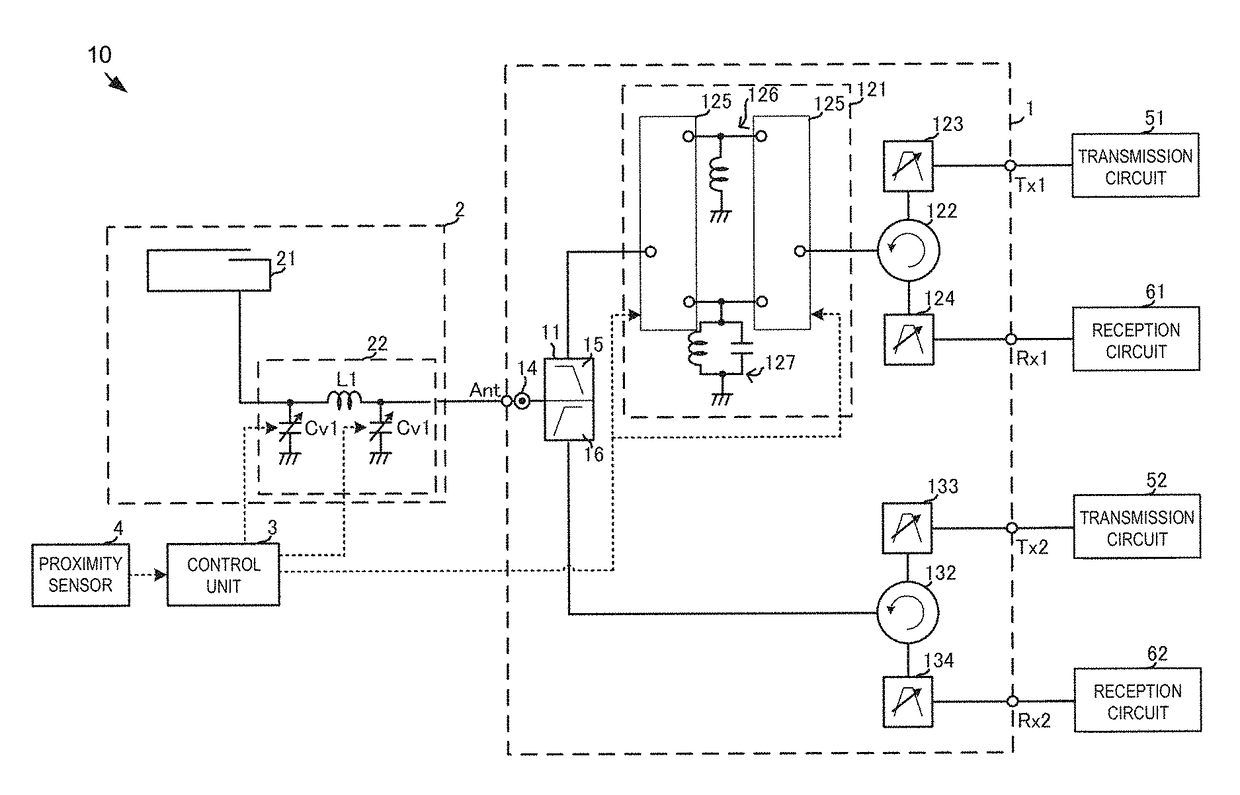
[0037]FIG. 3 is a circuit block diagram illustrating a front end circuit and a wireless communication device according to the present embodiment. A wireless communication device 10 according to the present embodiment transmits and receives using multiple communication bands on a low-frequency band side and multiple communication bands on a high-frequency band side. In the case of LTE, for example, a low-frequency band-side communication band is a communication band of approximately 1 GHz or lower. In the case of LTE, for example, a high-frequency band-side communication band is a communication band of approximately 1.4 GHz or higher.
[0038]The wireless communication device 10 includes a front end circuit 1, an antenna circuit 2, a control unit 3, a proximity sensor 4, transmission circuits 51 and 52, and reception circuits 61 and 62.
[0039]The front end circuit 1 transmits and receives in each communication band through the antenna circuit 2. As such, the front end circuit 1 has a tra...
second embodiment
[0070]A wireless communication device 10A and a front end circuit 1A according to a second embodiment of the present disclosure will be described next. FIG. 4 is a circuit block diagram illustrating the wireless communication device 10A and the front end circuit 1A according to the present embodiment. The wireless communication device 10A and the front end circuit 1A include matching circuits 126A and 127A instead of the matching circuits 126 and 127 described in the first embodiment. The matching circuits 126A and 127A are variable impedance circuits having variable reactance elements such as digital tuning capacitors (DTC).
[0071]When the current state is determined to be the antenna non-proximate state, the control unit 3 controls the variable matching circuit 121 to cause the high-frequency switch 125 to connect the matching circuit 126A to the signal path. Meanwhile, when the current state is determined to be the antenna proximate state, the control unit 3 controls the variable ...
third embodiment
[0075]A wireless communication device 10B and a front end circuit 1B according to a third embodiment of the present disclosure will be described next. FIG. 5 is a circuit block diagram illustrating the wireless communication device 10B and the front end circuit 1B according to the present embodiment. The wireless communication device 10B and the front end circuit 1B have switchplexers 122B and 132B and pluralities of duplexers 123B and 133B, instead of the circulators 122 and 132 as well as the transmission filters 123 and 133 and the reception filters 124 and 134 according to the first embodiment. The plurality of duplexers 123B handles respective low-frequency communication bands, and is constituted by a transmission filter and a reception filter that take those communication bands as their pass bands. The plurality of duplexers 133B handles respective high-frequency communication bands, and is constituted by a transmission filter and a reception filter that take those communicati...
PUM
 Abstract
Description
Claims
Application Information
 - R&D
- Intellectual Property
- Life Sciences
- Materials
- Tech Scout
- Unparalleled Data Quality
- Higher Quality Content
- 60% Fewer Hallucinations
Browse by: Latest US Patents, China's latest patents, Technical Efficacy Thesaurus, Application Domain, Technology Topic, Popular Technical Reports.
© 2025 PatSnap. All rights reserved.Legal|Privacy policy|Modern Slavery Act Transparency Statement|Sitemap|About US| Contact US: help@patsnap.com


