Antenna apparatus

a technology of antenna apparatus and antenna body, which is applied in the structure of resonant antennas, thermoelectric devices, radiating elements, etc., can solve the problems of unsolved problems in the conventional art, difficult design of antenna apparatus, and difficulty in achieving resonance with a large number of frequency components contained therein, so as to reduce the overall dimensions of the antenna apparatus, increase the number of resonance points, and increase the bandwidth

Inactive Publication Date: 2009-05-21
KONICA MINOLTA INC
View PDF7 Cites 2 Cited by
  • Summary
  • Abstract
  • Description
  • Claims
  • Application Information

AI Technical Summary

Benefits of technology

[0025]According to the invention of the Claim 1, when using the first and second radiating plates which are similar to each other in the plan view and are different from each other in the size, the number of resonance points is increased and the bandwidth is also increased as compared to the antenna apparatus using two radiating plates having almost the same shape.
[0026]Further, this antenna is an unbalanced antenna wherein the first and second radiating plates are different from each other in the size. This makes it possible to connect the unbalanced line directly to supply power, eliminating the need of separately installing an unbalanced / balanced conversion circuit or impedance conversion circuit, with the result that the overall dimensions of the antenna apparatus can be reduced.
[0027]According to the invention of the Claim 2, the radio wave is emitted uniformly to the right and left. This arrangement improves the emission pattern and ensures uniform directivity
[0028]According to the invention of Claim 3, the straight line of at least one of the first and second radiating plates does not cross the center line, and therefore, the number of resonance points is increased and the bandwidth is also increased.
[0029]According to the invention of Claim 4, the power supply section can be mounted on a desired position of the arc in response to the width of the space between the radiating plates, so that the impedance can be adjusted.
[0030]According to the invention of Claim 5, the straight line of at least one of the first and second radiating plates does not cross the reference line, and therefore, the number of resonance points is increased and the bandwidth is also increased. Further, since the center position of the radiating plate in the lateral direction is located on the reference line, the radio wave is radiated from the center position in the lateral direction of the radiating plate. This arrangement provides extremely uniform directivity of the antenna apparatus and improves the radiation pattern.

Problems solved by technology

Further, the UWB antenna apparatus uses an increased band frequency width, and this makes it difficult to achieve resonance with a great number of frequency components contained therein.
To put it another way, as the frequency of the radio wave to be sent and received is increased in bandwidth, the designing of the antenna apparatus becomes more difficult.
This problem remains unsolved in the conventional art.

Method used


Image

  • Antenna apparatus
  • Antenna apparatus
  • Antenna apparatus

Examples


embodiment 1

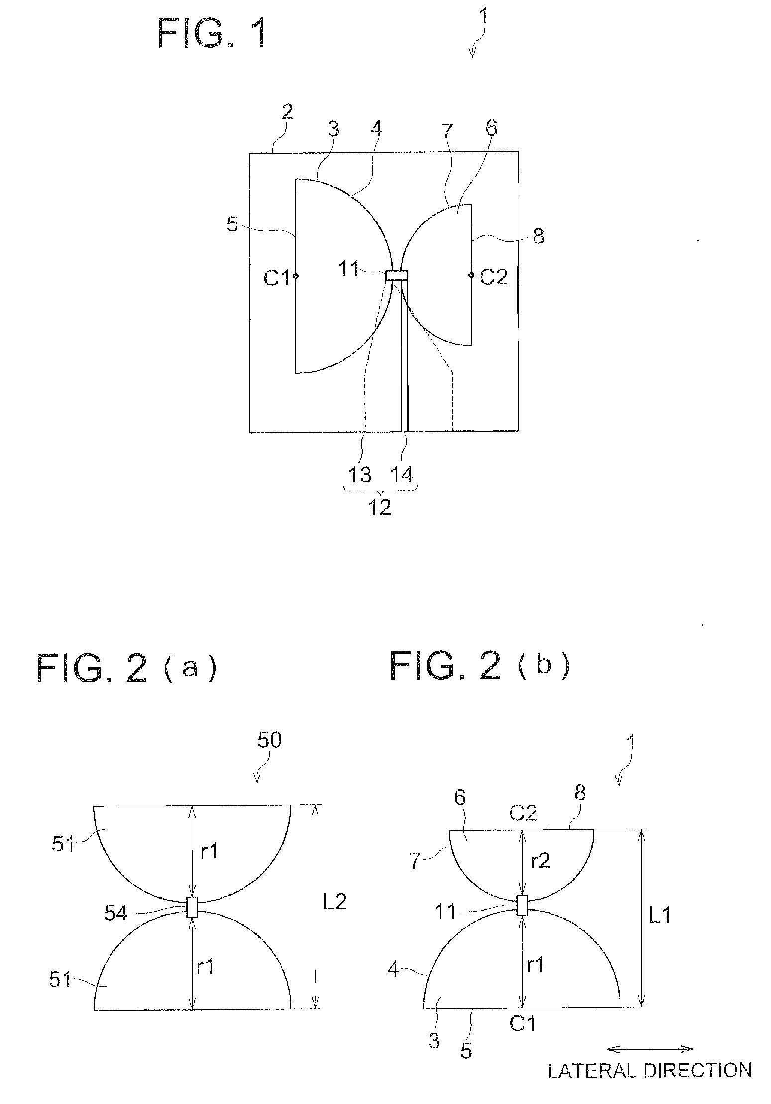
[0057]The following describes the structure of the antenna apparatus 1 as a first embodiment.

[0058]As shown in FIG. 1, the antenna apparatus 1 of the present invention is provided with an electronic substrate 2. A first radiating plate 3 of semicircular shape in the plan view is arranged on the upper side of the electronic substrate 2. As shown in FIG. 2 (b), the first radiating plate 3 is formed of a radius r1 wherein a center point C1 is used as the center of a circle. As shown in FIG. 2 (b), the first radiating plate 3 is provided with a first circular arc 4 as one arc-shaped side, and a first straight line 5 of linear shape passing through both ends of the first circular arc 4 and the center point C1.

[0059]The second radiating plate 6 exhibiting the plan view similar to the first radiating plate 3 is mounted on the upper side of the electronic substrate 2 located face to face with the vertex of the circular arc of the first radiating plate 3, wherein the vertexes of the circular...

embodiment 2

[0074]Referring to FIG. 5, the following describes the structure of the antenna apparatus 20 of the second embodiment. The same structures as those of the first embodiment are assigned with the same numerals of reference.

[0075]The antenna apparatus 20 of the present embodiment includes the same electronic substrate as that of the first embodiment. The upper side of the electronic substrate is provided with the same first radiating plate 3 with radius r1 and center point C1 as that of the first embodiment. As shown in FIG. 5 (b), the second radiating plate 6 similar to the first radiating plate 3 is arranged at the position face to face with the first circular arc 4. The second radiating plate 6 is designed to have the radius r2 and center point C2. Assuming that the line connecting the center points C1 and C2 forms a center line CL, the first radiating plate 3 is arranged in such a way that the first straight line 5 is perpendicular to the center line CL. The second radiating plate ...

embodiment 3

[0093]The following describes the structure of the antenna apparatus 30 of the third embodiment: The same structures as those of the first embodiment are assigned with the same numerals of reference, and description is omitted to avoid duplication.

[0094]The antenna apparatus 30 is provided with the same electronic substrate as that of the first embodiment. The upper side of the electronic substrate is provided with the same first radiating plate 3 with radius r1 and center point C1 as that of the first embodiment. As shown in FIG. 8 (b), the second radiating plate 6 similar to the first radiating plate 3 is arranged at the position face to face with the first circular arc 4. The second radiating plate 6 is designed to have the radius r2 and center point C2.

[0095]Assuming that the line connecting the center position of the first radiating plate 3 in the lateral direction and the center position of the second radiating plate 6 in the lateral direction is a reference line RL, the first...


PUM


Abstract

An antenna device reduced in size and increased in bandwidth. The antenna device comprises a first radiating plate and a second radiating plate arranged with a space having a predetermined width. A power supply section feeding a power to the first radiating plate and the second radiating plate is installed in the space. The first radiating plate and the second radiating plate are characterized in that they are similar to each other in plan view shape and different in size from each other.

Description

FIELD OF THE INVENTION[0001]The present invention relates to an antenna apparatus, particularly to an antenna apparatus for UWB (Ultra Wide Band).BACKGROUND[0002]A UWB antenna apparatus is known in the conventional art as an antenna apparatus capable of using the frequency band characterized by an ultra wide-band. The UWB in the sense in which it is used here refers to the ultra wide-band in a wireless transmission system using a wide-band frequency width (several GHz through several tens of GHz) wherein a short pulse of 1 ns or less is employed. The UWB antenna apparatus is characterized by ultra low output transmission and very small interference with other wireless communications.[0003]For example, the UWB antenna apparatus 50 is known in the conventional art, as shown in FIG. 11. This antenna apparatus is provided with a pair of radiating plates (conducting plates) 51, 51. The radiating plates 51 are semicircular in plan view, and are arranged at a space having a predetermined w...

Claims


Application Information

Patent Timeline
Patent Type & Authority Applications(United States)
IPC IPC(8): H01Q1/36H01Q5/10
CPCH01Q9/285
Inventor KOSHIJI, FUKUROEGUCHI, TOSHIYA
Owner KONICA MINOLTA INC
Why Eureka
Try Eureka