
Data dependent drive scheme and display

a drive scheme and display technology, applied in the field of display driving schemes and displays, can solve the problems of increasing the amount of heat generated by the display system, increasing the power consumption of the display system, and increasing the amount of power consumed to cool the system, so as to facilitate the disabling of particular display systems, the effect of reducing power consumption and heat build-up

Active Publication Date: 2009-12-10
OMNIVISION TECH INC
View PDF101 Cites 10 Cited by
  • Summary
  • Abstract
  • Description
  • Claims
  • Application Information

AI Technical Summary

Benefits of technology

[0010]The present invention overcomes the problems associated with the prior art by providing a novel display driver and method in order to reduce power consumption and heat build-up within the display driver and associated display system. In particular, the invention facilitates disabling particular display system and display driver operations depending on the display data.

Problems solved by technology

Conversely, an increase in power consumed in a display system will increase the amount of heat generated by that display system.
In addition, often when excess heat is generated, still more power is consumed to cool the system by powering cooling components.
As described above, one of the most important reasons is that power consumption is directly tied to the amount of waste heat that a display system generates.
Furthermore, conserving power increases battery life in portable electronic devices, especially those with high-resolution displays that require high bandwidths to supply image data and control signals to the display.
Additionally, excessive heat can damage many of the display system components over time and degrade display performance and / or cause catastrophic device failure.
For example, the image quality of liquid crystal displays is susceptible to excessive heat build up.
Such light sources often generate large amounts of heat near display components also degrading their performance over time and / or causing catastrophic failure.

Method used


Image

  • Data dependent drive scheme and display
  • Data dependent drive scheme and display
  • Data dependent drive scheme and display

Examples


Embodiment Construction

[0034]The present invention overcomes the problems associated with the prior art by providing a system and method that reduces power consumption and heat build-up within a display system. In the following description, numerous specific details are set forth (e.g., particular display driver components, particular data and voltage busses, etc.) in order to provide a thorough understanding of the invention. Those skilled in the art will recognize, however, that the invention may be practiced apart from these specific details. In other instances, details of well-known display driving practices (e.g. routine optimization, component synchronization specifics, etc.) and components have been omitted, so as not to unnecessarily obscure the present invention.

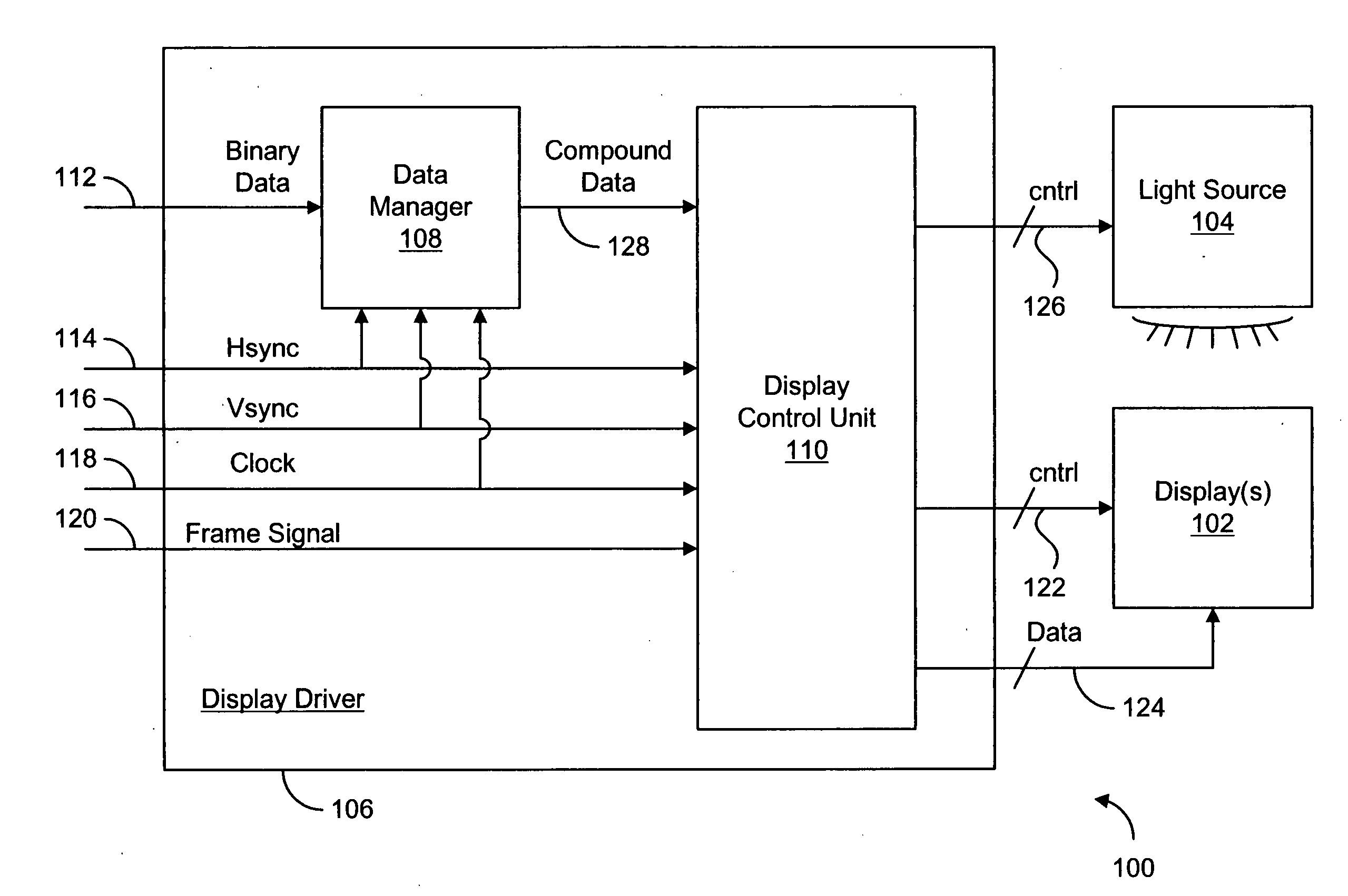
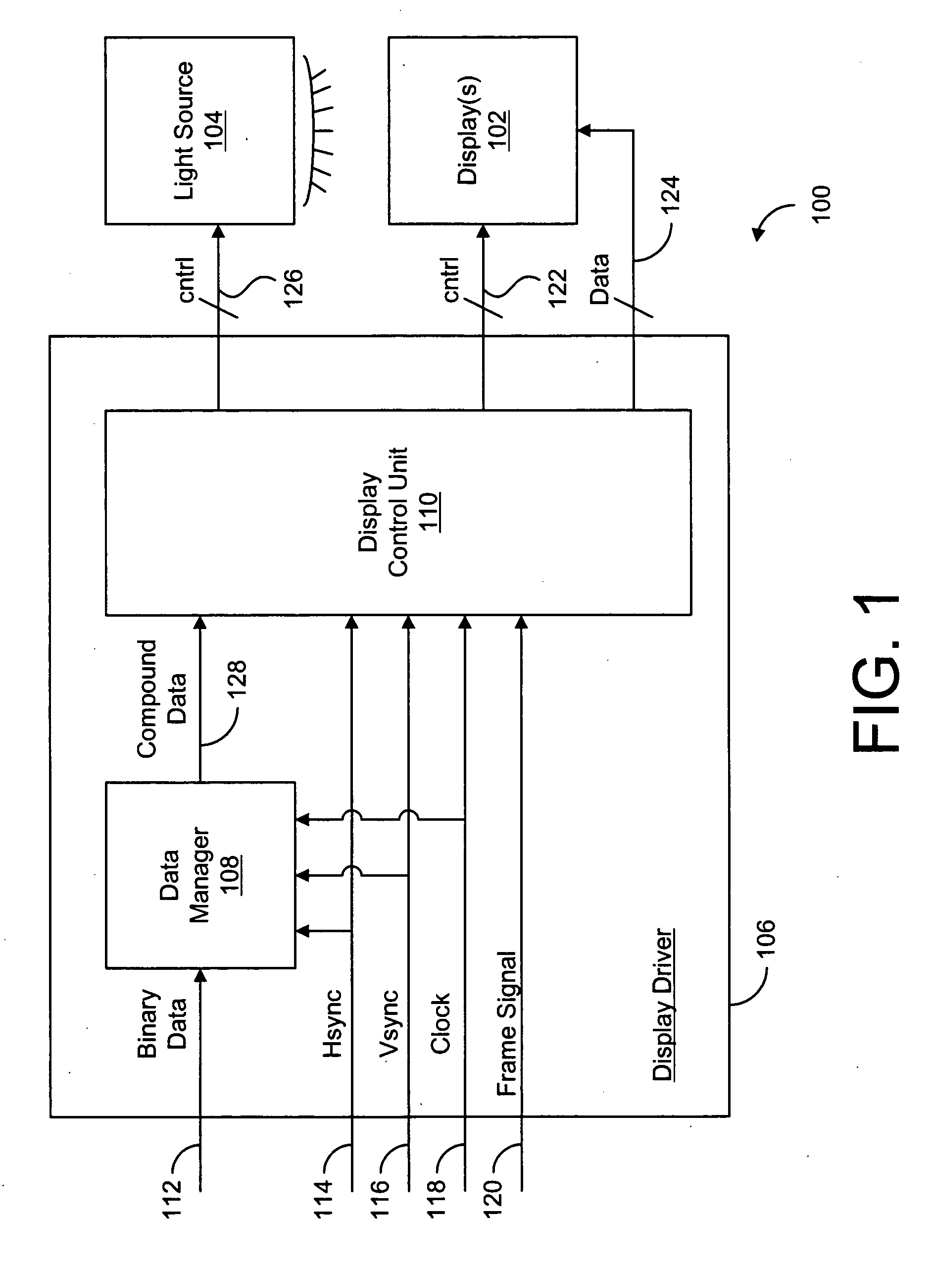
[0035]FIG. 1 shows a block diagram of a display system 100 according to one embodiment of the present invention. Display system 100 includes one or more display(s) 102 (one in the current embodiment) for displaying image data, a light sou...


PUM


Abstract

A method for writing data to a display includes the steps of receiving a plurality of data bits, where each bit is associated with a different pixel of the display, reading the value of each data bit, determining whether each data bits has an off-state value, and generating a disable signal if each data bit has an off-state value. Responsive to a disable signal, the method further includes suspending the transfer of data to the pixels of the display, turning off a light source (e.g., an LED, laser, etc.) for a time period dependent on the significance of at least one of the data bits, and / or forcing each pixel of the display into an off state for a time period dependent on the significance of at least one of the data bits. A display driver circuit for performing the methods of the present invention is also disclosed.

Description

BACKGROUND[0001]1. Field of the Invention[0002]This invention relates generally to display driving schemes and displays and more particularly to a system and method for disabling particular display and display driver operations during display modulation based on the display data.[0003]2. Description of the Background Art[0004]Decreasing power consumption and heat generation in display systems have always been important design criteria for display engineers. This has especially been the case in recent years because displays (e.g., televisions, computer monitors, micro-LCDs, etc.) have been increasing in size and / or resolution. For example, displays having a resolution of at least 1920×1080 pixels are now common, as are displays that are larger than fifty inches diagonally.[0005]As will be described below, lowering power consumption and heat generation are sympathetic goals. Often, lowering power consumption in a display system will also lower the amount of heat generated by the displ...

Claims


Application Information

Patent Timeline
Patent Type & Authority Applications(United States)
IPC IPC(8): G09G5/00
CPCG09G3/2029G09G3/2033G09G3/2037G09G3/3406G09G3/3611G09G2360/18G09G2310/0235G09G2310/063G09G2320/064G09G2330/021G09G5/399
Inventor NG, SUNNY YAT-SAN
Owner OMNIVISION TECH INC
Learn More