Device for cleaning wiper elements for an inkjet print head

a technology of inkjet printing and wiper elements, which is applied in the direction of printing, ticket-issuers, franking apparatus, etc., can solve the problems of high maintenance cost, inability to suction the excess ink from the sponge element, and inability to achieve the effect of cost-effective removal of excess ink, improved maintenance, and no additional cos

Active Publication Date: 2009-12-10
FRANCOTYP POSTALIA
View PDF7 Cites 3 Cited by
  • Summary
  • Abstract
  • Description
  • Claims
  • Application Information

AI Technical Summary

Benefits of technology

[0009]An object of the present invention is to improve the maintenance and to achieve a device for cleaning wiper elements in an inkjet printing apparatus, wherein depositing and drying of excess ink residues on the wiper elements is avoided due to the action of the device. The cleaning of the wiper elements should be enabled independent of the movement of the print head and should be integrated into the maintenance workflow of the printing group without additional cost.
[0010]The object is achieved in accordance with the invention by a cleaning device for an inkjet print head having an ink uptake unit that passively takes up ink into the uptake unit itself and that is arranged on the chassis of the printing apparatus at a point past which a maintenance station moves, the maintenance station traveling in at least one direction. The maintenance station has wiper elements that dispense ink to the ink uptake element during the passing movement. The ink uptake unit is advantageously a sponge module formed by a sponge mount, a sponge body and a mounting plate. The sponge body binds the ink by suction due to the capillary effect and thus cost-effectively removes the excess ink after every wiping procedure by the wiper elements (i.e. immediately after the wiping of the print head surface) when the maintenance station is moved, or the carriage of the RDS returns from the wiping to its initial position. It can therefore be ensured that the wiper elements wipe across the print head only when they are in a clean state. The sponge module is mounted stationary in the rear part of the chassis as an independent module, so that the sponge element can itself easily be exchanged when the RDS has traveled into the sealing position in the forward part. Automated suctioning of the ink from the sponge is not necessary, so that a simpler and cost-effective embodiment is achieved relative to the solution according to EP 885 726 A1.

Problems solved by technology

The solution is expensive because more ink that must be wiped off and absorbed by the sponge also collects on the much larger (in comparison to HP print heads) print head surface of the special print head of the Jetmail®.
Since, due to the large amount of ink, the absorption capacity of the sponge is soon exceeded, time-consuming and costly measures for suctioning the excess ink from the sponge element are required for maintenance.
It has been empirically established that the strippers previously used in the franking machine of the Centormail® type to clean the wiper lips are often insufficient, such that ink residues dry on the wiper elements.
In many cases the dried ink has polluting effects upon a new wiping of the damp heads, which reduce the print quality or possibly could lead to failure of the print head.

Method used


Image

  • Device for cleaning wiper elements for an inkjet print head
  • Device for cleaning wiper elements for an inkjet print head
  • Device for cleaning wiper elements for an inkjet print head

Examples


Embodiment Construction

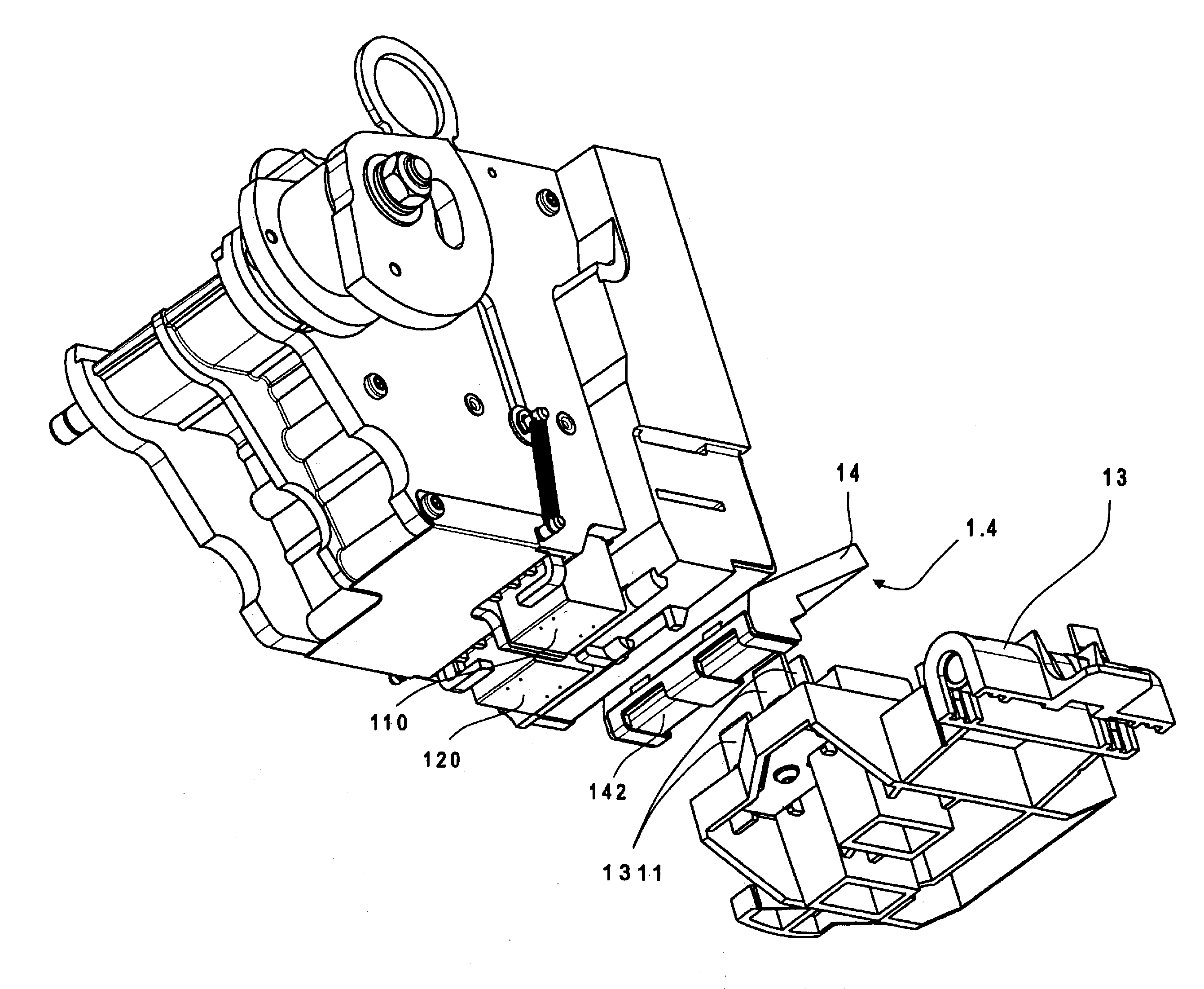
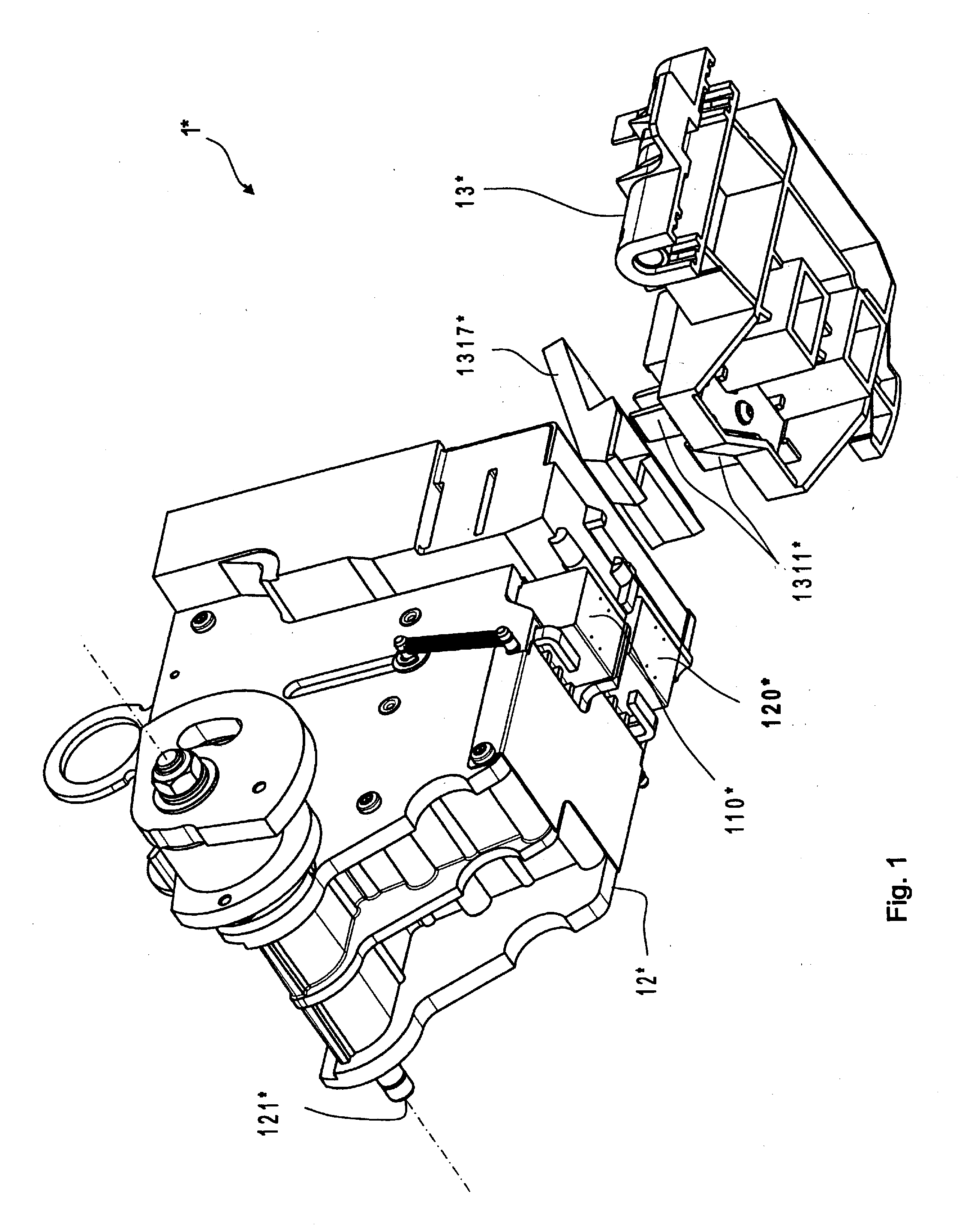
[0018]A perspective view of the known device 1* of the franking machine of the Centormail® type is shown in FIG. 1, seen from the front lower right. A print head receptacle 12* carries two inkjet print heads 110*, 120* and is shown pivoted on an axis 121* into a cleaning position. A cleaning and sealing device (RDS) 13* that carries wiper elements 1311* has been moved into a starting position in the rear part of the franking machine. A stripper mount 1317* is arranged between the RDS 13* and the print head receptacle 12*. The stripper mount carries strippers on its downward facing edges, at which strippers the stripped ink initially drips down. However, a residue of ink remains clinging due to adhesion and can then dry.

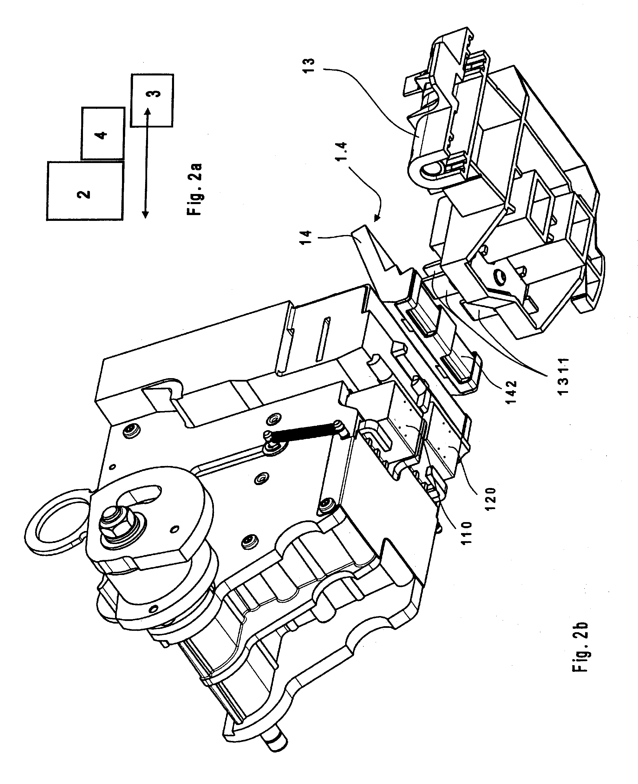
[0019]The basic configuration of the arrangement of a few modules of an inkjet printing device in connection with the device according to the invention for cleaning of wiper elements is explained using FIG. 2a. An ink dispenser 2 and an ink uptake unit 4 are arranged ...


PUM


Abstract

In a device to clean wiper elements of an inkjet print head of an ink dispenser of a printing apparatus having a chassis, a maintenance station is mounted on the chassis to allow travel of the maintenance station in at least one direction that causes the maintenance station to move past the inkjet print head. The maintenance station carries wiper elements that wipe ink from the surface of the inkjet print head as the maintenance station moves past the inkjet print head. An ink uptake unit is mounted at the chassis at a position past which the maintenance station travels, after traveling past the inkjet print head. The ink uptake unit includes material that transfers ink from the wipers to the material.

Description

BACKGROUND OF THE INVENTION[0001]1. Field of the Invention[0002]The present invention concerns a device for cleaning wiper elements for an inkjet print head of an ink dispenser. The invention is suitable for an inkjet printing device that is used for mail processing, addressing and franking machines, and other inkjet printing apparatuses.[0003]2. Description of the Prior Art[0004]The use of a sponge element in a franking machine of the Jetmail® type is described in European patent application EP 885 726 A1. This sponge element is attached to the print head and serves to wipe off the wiper lips that are arranged on the carriage of a cleaning and sealing station (RDS). The solution is expensive because more ink that must be wiped off and absorbed by the sponge also collects on the much larger (in comparison to HP print heads) print head surface of the special print head of the Jetmail®. Since, due to the large amount of ink, the absorption capacity of the sponge is soon exceeded, time...

Claims


Application Information

Patent Timeline
Patent Type & Authority Applications(United States)
IPC IPC(8): B41J2/165
CPCB41J2/16535B41J2/16541G07B2017/00556G07B2017/00532B41J2/16588
Inventor MUHL, WOLFGANGORTMANN, AXEL
Owner FRANCOTYP POSTALIA
Why Eureka
Try Eureka