

Shift register and shift register unit for diminishing clock coupling effect
- Summary
- Abstract
- Description
- Claims
- Application Information
AI Technical Summary
Benefits of technology
Problems solved by technology
Method used
Image

Examples
second embodiment
[0047]Further referring to FIG. 6A to FIG. 6H, which illustrate various signal waveforms of the shift register unit 203b according to the present invention, which depict the lowest level of each of the first clock signal (CKO), the second clock signal (XCKO) and a setting signal (STN−1) generated from the previous stage shift register unit 203b and an input signal of the input node (Q) of the shift register unit 203b is the same as the level of the first source voltage (VSS1), but the lowest level of each of the first periodic signal (CKE), the second periodic signal (XCKE), the signal of the first input node (K) of the first pull-down module 320a and the signal of the second input node (P) of the second pull-down module 320b is the same as the level of the second source voltage (VSS2).
third embodiment
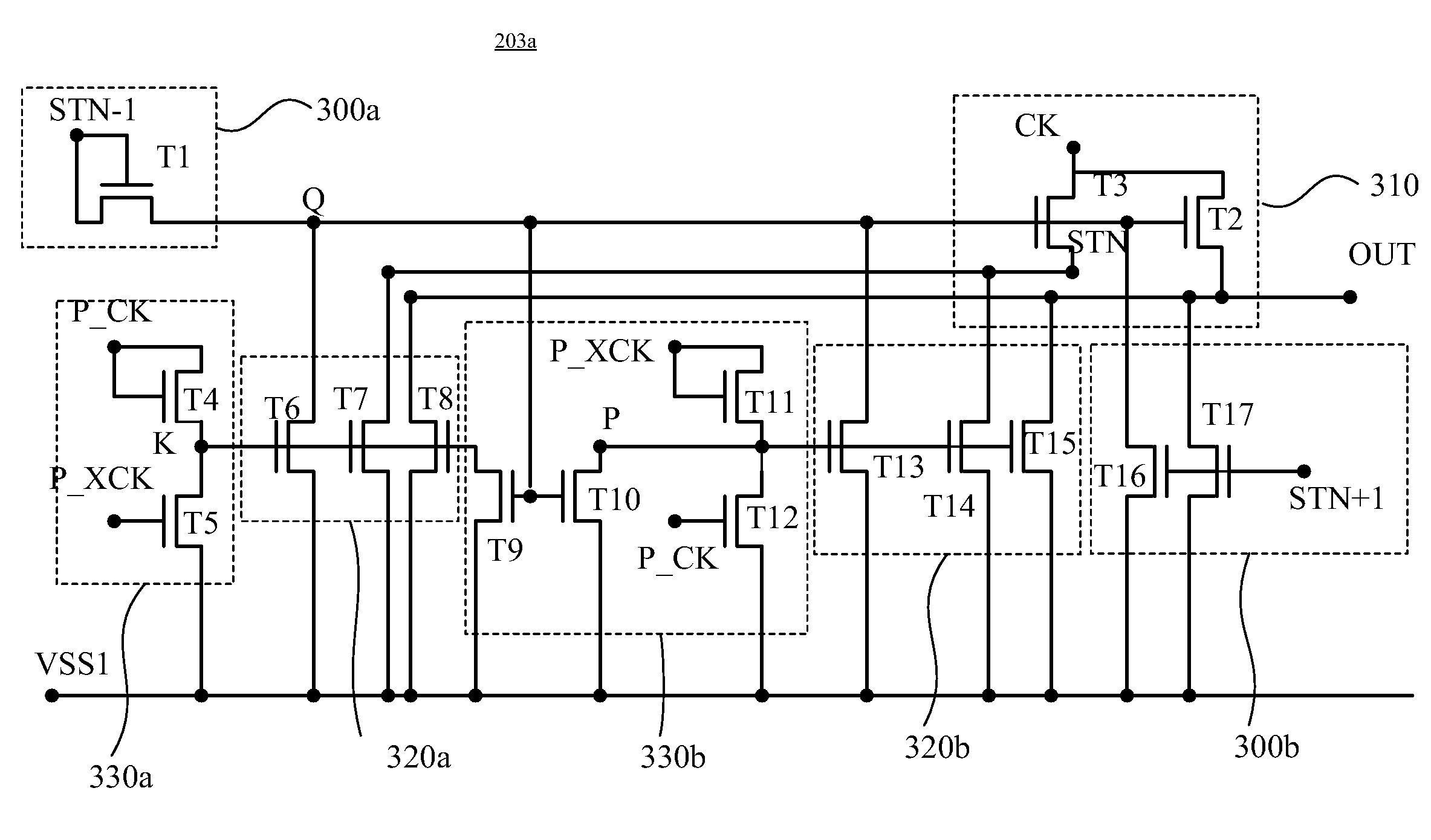
[0048]Further referring to illustration of FIG. 3C, a shift register unit 203c according to a third prefer embodiment of the present invention is introduced herein. As the same as shown in FIG. 2, the shift register unit 203c can be one of the odd-stage cascaded shift register unit (e.g. GOA1, GOA3, GOA5 . . . GOAN) and the even-stage cascaded shift register units (e.g. GOA2, GOA4, GOA6 . . . GOAN+1). The shift register unit 203c of the third embodiment is designed only for connecting the first signal (CK), the second signal (XCK) and the fourth signal (P_XCK), and primarily comprises a first pull-up driving module 300a, a second pull-up driving module 300b, a pull-up module 310, a pull-down module 320, and a pull-down driving module 330.
[0049]The first pull-up driving module 300a of the shift register unit 203c comprises a first transistor (T1) having a drain and a gate both jointed to a pulse signal, such as a setting signal (STN−1) generated from the previous stage shift register...
PUM
 Abstract
Description
Claims
Application Information