
Serpentine cooling circuit and method for cooling tip shroud

Active Publication Date: 2009-12-10
GENERAL ELECTRIC CO
View PDF14 Cites 39 Cited by
  • Summary
  • Abstract
  • Description
  • Claims
  • Application Information

AI Technical Summary

Benefits of technology

[0006]The present invention proposes to more effectively cool the blade tip shroud by providing for serpentine cooling thereof, primarily at but not limited to the fillets between the airfoil and the tip shroud. The invention further provides a method of cooling a tip shroud using such a serpentine circuit.

Problems solved by technology

However, integral shrouds on rotating airfoils are highly stressed parts due to the mechanical forces applied via the rotational speed.
The high temperature environment coupled with the high stresses makes it a challenge to design a shroud that will effectively perform over the entire useful life of the remainder of the blade.
Reducing the tip shroud coverage, however, results in a detriment to engine performance.

Method used


Image

  • Serpentine cooling circuit and method for cooling tip shroud
  • Serpentine cooling circuit and method for cooling tip shroud
  • Serpentine cooling circuit and method for cooling tip shroud

Examples


Embodiment Construction

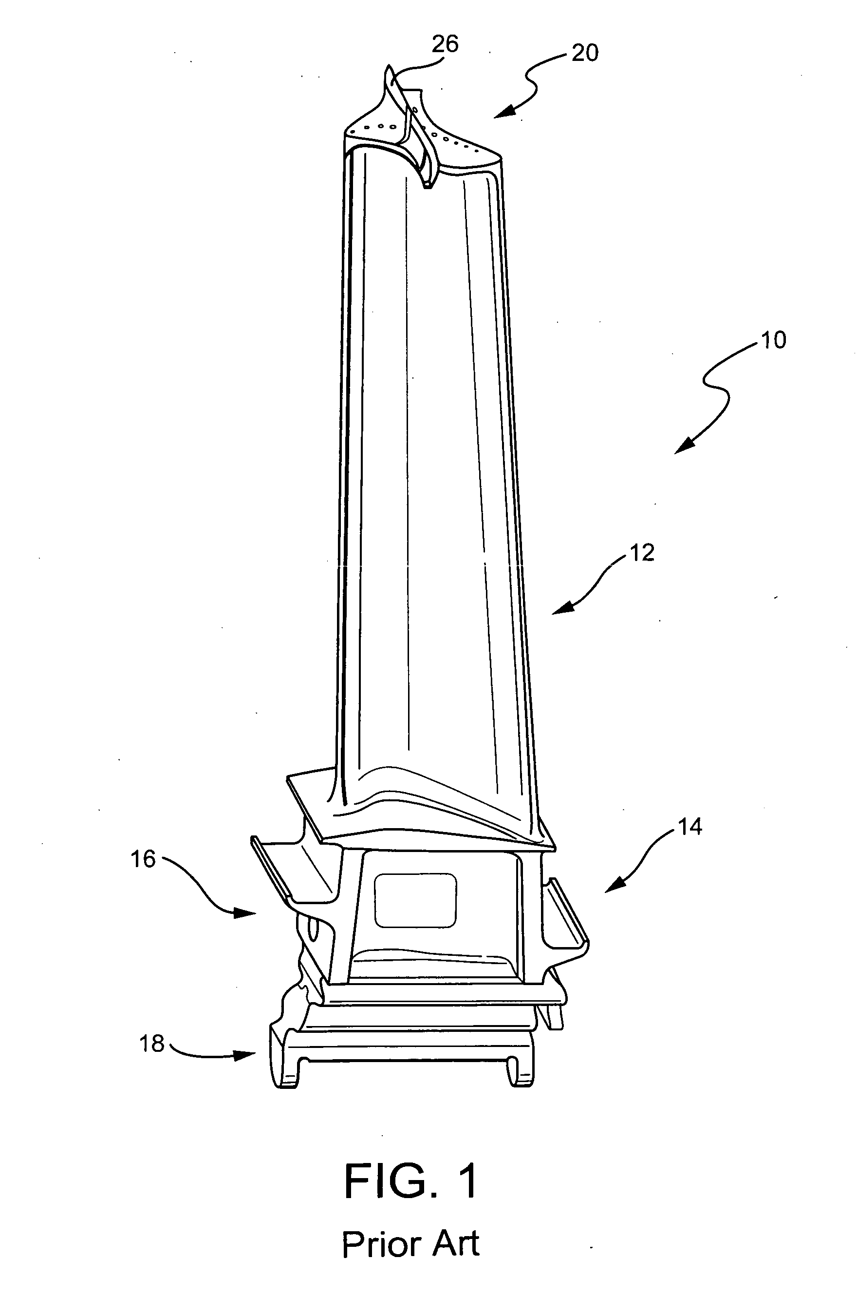
[0016]A typical blade with cooling passages exiting at the blade tip to flow over the tip shroud is schematically illustrated in FIG. 1. As schematically illustrated therein, each turbine blade 10 is comprised of an airfoil portion 12 and a root portion 14. The airfoil portion has a leading edge and a trailing edge. A generally concave surface and a generally convex suction surface extend between the leading and trailing edges on opposing sides of the airfoil. In the illustrated example, the blade root 14 is comprised of a shank 16 and a dovetail 18 to engage a corresponding dovetail groove on the rotor to secure the blade to the rotor.

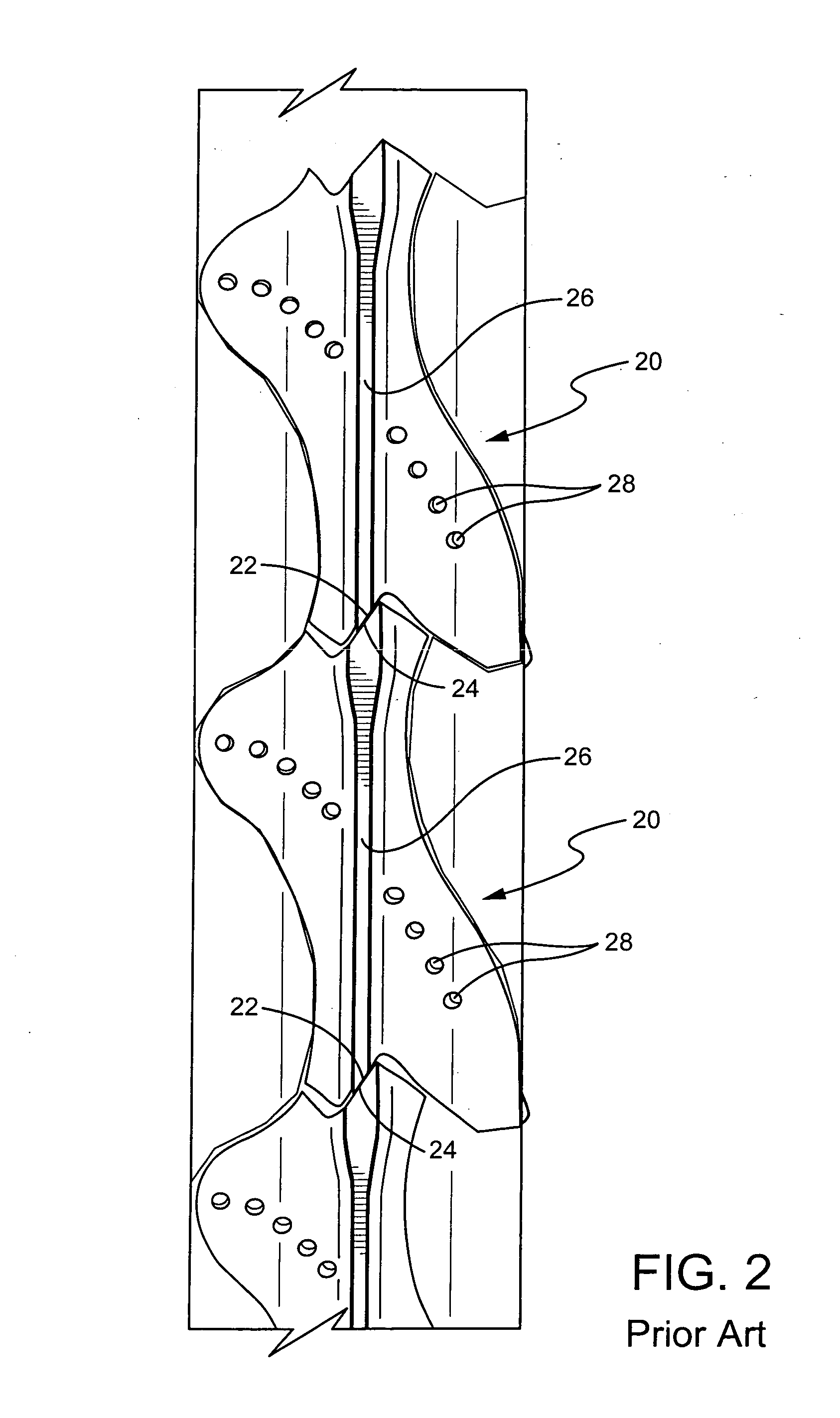
[0017]As shown in FIGS. 1 and 2, a shroud 20 is formed at the tip of the airfoil 12 and extends outwardly from the airfoil. The shroud thus has radially inward and radially outward facing surfaces and is exposed to the hot compressed gas flowing through the turbine section. Each shroud has bearing surfaces 22,24 over which it contacts a shroud of an a...


PUM


Abstract

A serpentine cooling circuit is formed in a gas turbine blade to cool portions of the tip shroud, primarily the fillet between the airfoil and the tip shroud and the shroud edges.

Description

BACKGROUND OF THE INVENTION[0001]The present invention relates to a blade for a turbine, e.g. aircraft engine, gas turbine, steam turbine, etc. More specifically, the present invention relates to the cooling of a turbine blade tip shroud. As a non-limiting example the invention and its background are described with reference to a gas turbine.[0002]A gas turbine is typically comprised of a compressor section that produces compressed air. Fuel is mixed with a portion of the compressed air and burned in one or more combustors, thereby producing hot compressed gas. The hot compressed gas is expanded in a turbine section to produce rotating shaft power. The turbine section is typically comprised of a plurality of alternating rows of stationary vanes (nozzles) and rotating blades (buckets). Each of the rotating blades has an airfoil portion and a root portion by which it is affixed to a rotor.[0003]Since the blades are exposed to the hot gas discharged from the combustors, cooling methods...

Claims


Application Information

Patent Timeline
IPC IPC(8): F01D5/18
CPCF01D5/187F01D5/225F05B2240/33F05D2250/185F05D2240/81Y02T50/676F05D2250/183F05D2250/184F05D2260/22141Y02T50/671Y02T50/60F01D5/00F01D5/08F01D25/08F01D25/12
Inventor BRITTINGHAM, ROBERT ALANWARD, JOHN D.
Owner GENERAL ELECTRIC CO
Features
  • Generate Ideas
  • Intellectual Property
  • Life Sciences
  • Materials
  • Tech Scout
  • Unparalleled Data Quality
  • Higher Quality Content
  • 60% Fewer Hallucinations
Learn More