Electroformed liquid jet surgical instrument

a liquid jet surgical and electro-mechanical technology, applied in the field of electro-mechanical liquid jet surgical instruments, can solve the problems of site of operation, unobservable, etc., and achieve the effect of minimizing the number and complexity of manufacturing steps

Inactive Publication Date: 2009-12-10
HYDROCISION
View PDF15 Cites 62 Cited by
  • Summary
  • Abstract
  • Description
  • Claims
  • Application Information

AI Technical Summary

Benefits of technology

[0008]Another major challenge in making liquid jet instruments for medical and surgical use is the need for large scale manufacture of precisely and reproducibly dimensioned jet-forming nozzles or orifices, and the need to accurately and reproducibly align them within the instrument, while minimizing the number and complexity of manufacturing steps.

Problems solved by technology

One of the major challenges in designing and manufacturing surgical instruments is that the instruments, or at least the parts of the system that contact the patient, are preferably disposable after the completion of the procedure.
Moreover, the site of operation can be in the interior of the body and may not be readily observable.
A further challenge in manufacturing for medical use is that a 180-degree bend in the path of the high pressure fluid may be required for certain configurations, so that the liquid jet is directed back in the direction from which the liquid is supplied.
Another major challenge in making liquid jet instruments for medical and surgical use is the need for large scale manufacture of precisely and reproducibly dimensioned jet-forming nozzles or orifices, and the need to accurately and reproducibly align them within the instrument, while minimizing the number and complexity of manufacturing steps.

Method used


Image

  • Electroformed liquid jet surgical instrument
  • Electroformed liquid jet surgical instrument
  • Electroformed liquid jet surgical instrument

Examples


Embodiment Construction

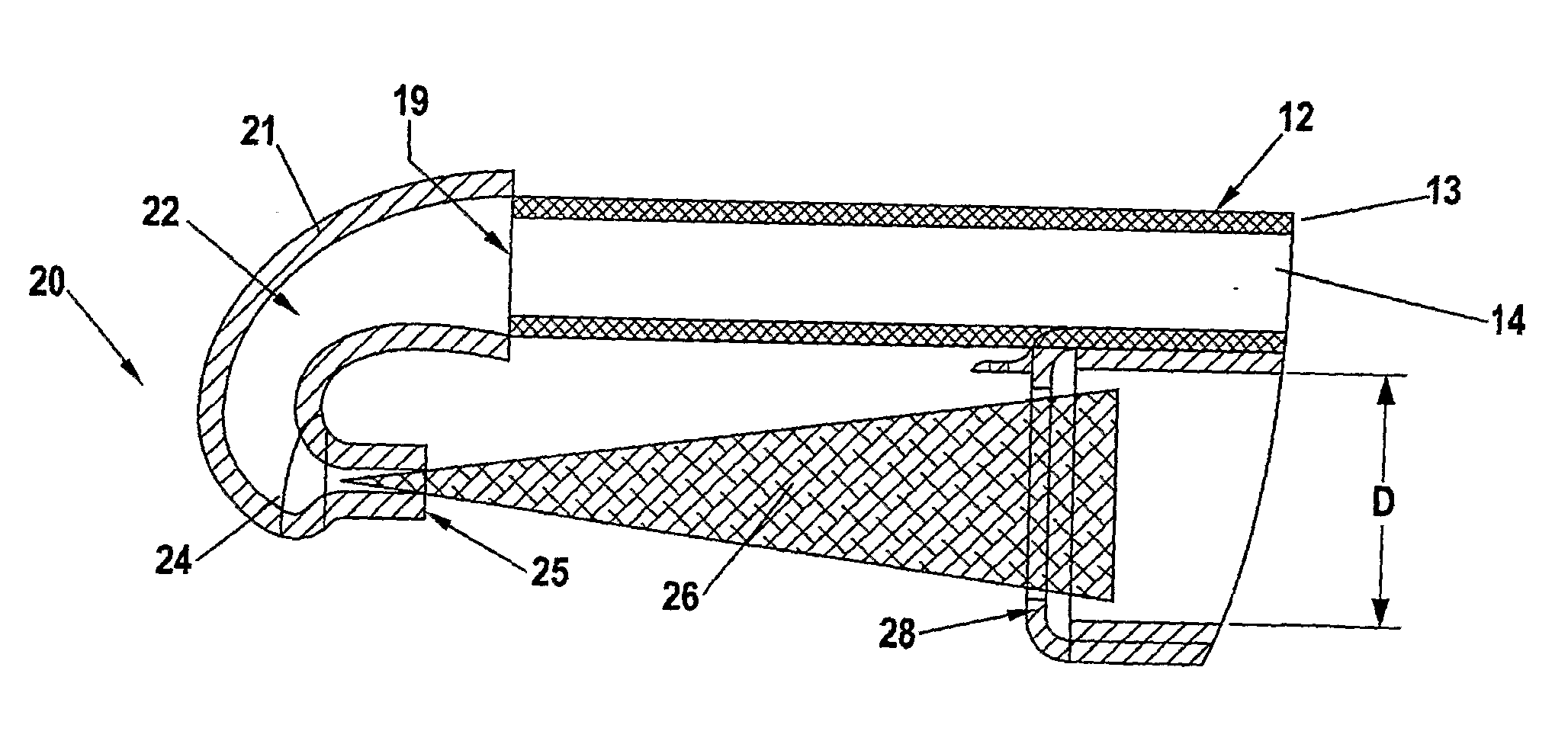
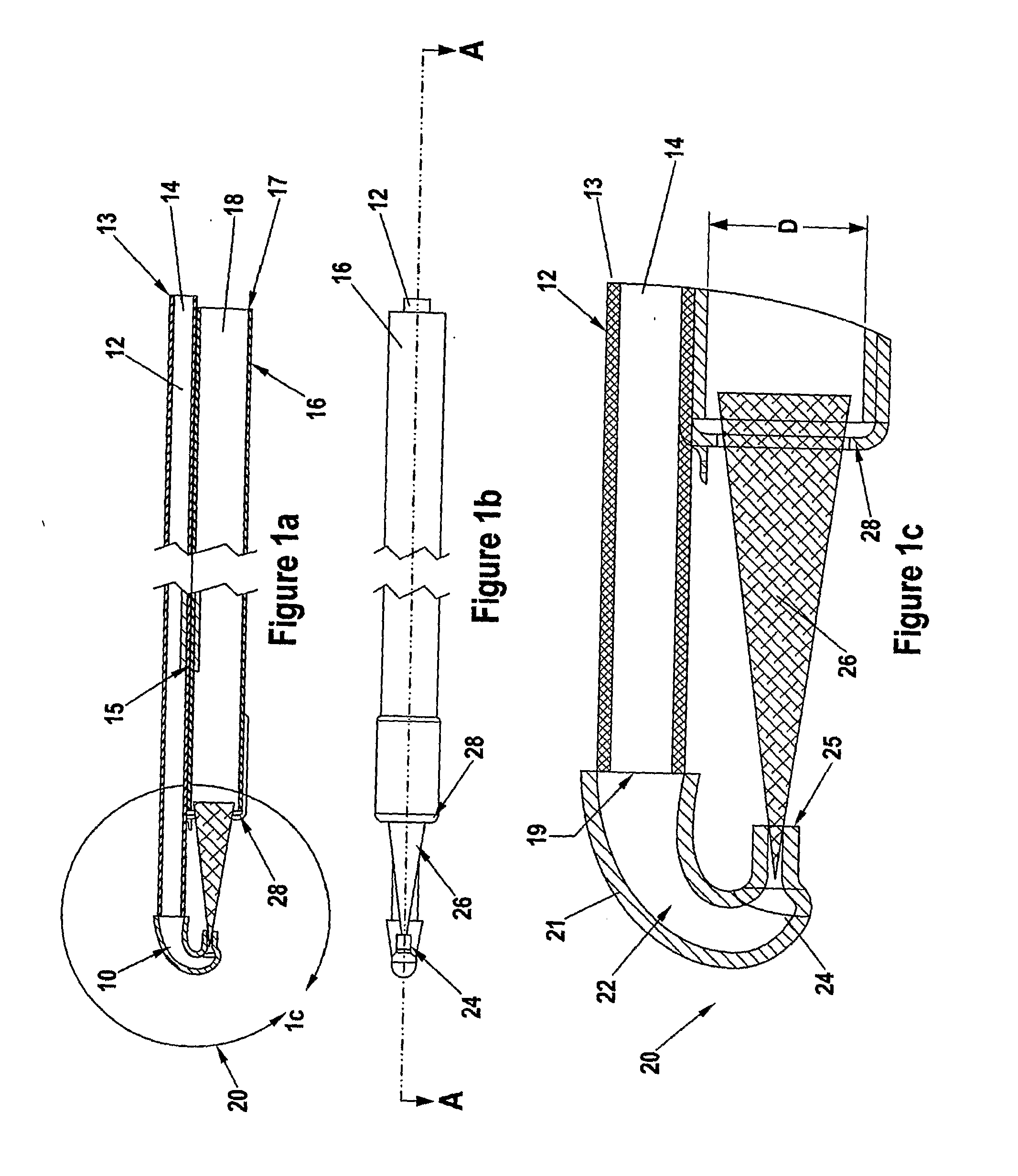
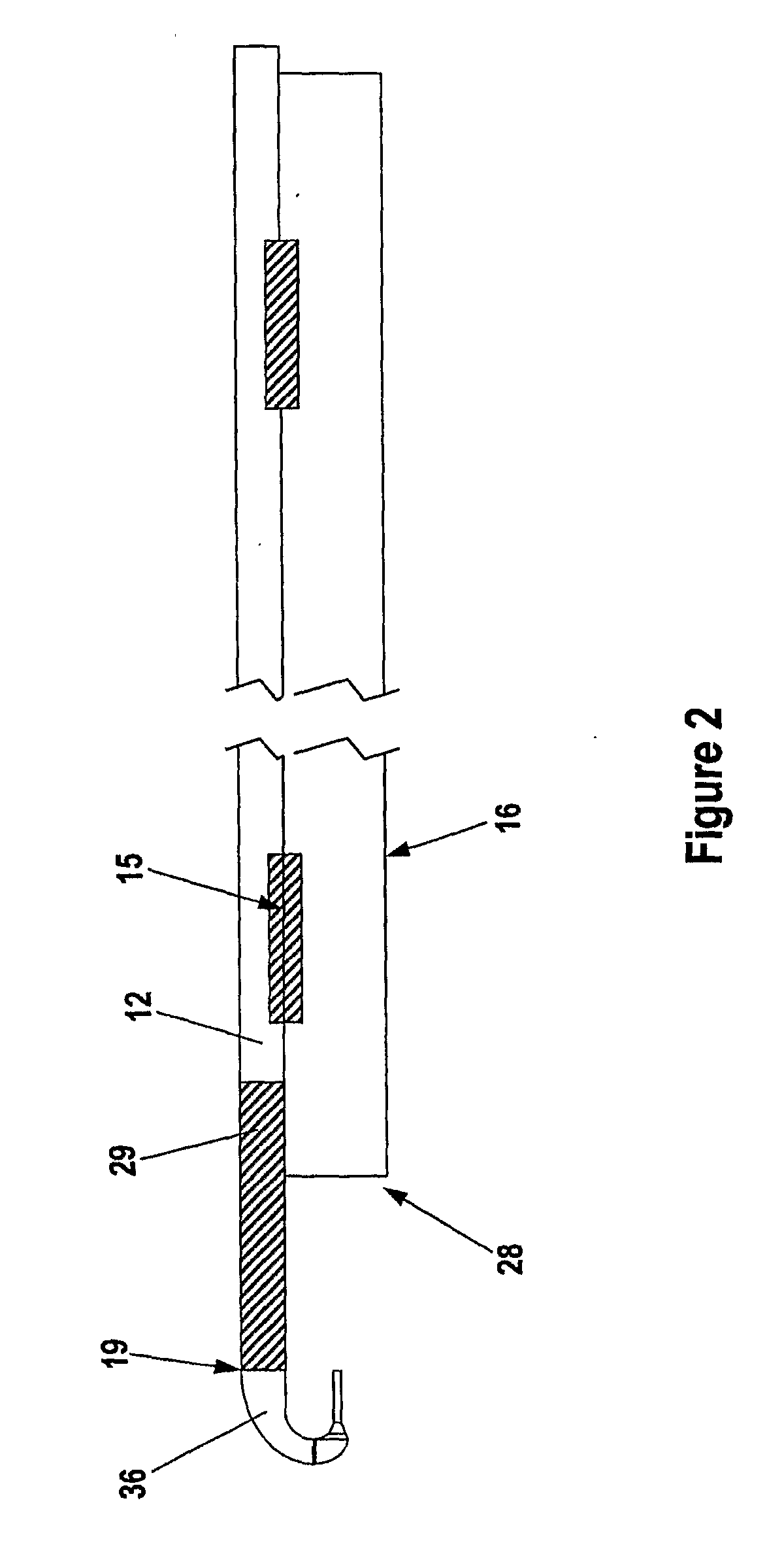
[0048]Disclosed here are inventive methods for manufacturing a variety of liquid jet instruments useful in a variety of applications and a variety of inventive liquid jet instruments formed by the instruments. Certain embodiments of the inventive instruments are especially well suited for a variety of surgical procedures. Certain embodiments of the liquid jet instruments provided by the invention can be configured in a variety of different ways for use in various surgical operating fields. Certain surgical instruments, according to the invention, are configured as surgical handpieces having a proximal end with a grasping region, or handle, shaped and configured to be comfortably held by the hand of an operator. The instruments may also have a distal end that includes at least one nozzle for forming a liquid jet. The distal end of certain embodiments of the inventive surgical instruments can be used to perform a surgical procedure on a patient. The invention may also be practiced uti...


PUM

PropertyMeasurementUnit
thicknessaaaaaaaaaa
diameteraaaaaaaaaa
temperatureaaaaaaaaaa

Abstract

Certain embodiments of the invention provide a variety of methods of manufacturing a liquid jet-forming surgical instrument. According to these methods, a nozzle assembly of the instrument is electroformed on a mandrel. The nozzle assembly includes a nozzle providing a jet-opening, wherein the nozzle is shaped to form a liquid jet. In some embodiments, the mandrel includes a first mandrel portion and a second mandrel portion. Once the nozzle assembly is formed, the mandrel may be removed from the nozzle assembly. The nozzle assembly may in certain embodiments be coupled to an outlet of the pressure tube. In certain embodiments, an inlet of an evacuation tube is positioned such that a jet-receiving opening of the evacuation tube is positioned opposite the jet-opening of the nozzle.

Description

FIELD OF THE INVENTION[0001]The invention relates generally to surgical instruments for creating a liquid jet and methods for making the instruments.BACKGROUND OF THE INVENTION[0002]Liquid jet cutting instruments for industrial cutting operations are known, and have been adapted for smaller scale and more delicate procedures. In particular, certain such devices have been adapted for use in surgical procedures. Many changes are needed for successful adaptation of industrial cutting for surgical / medical use.[0003]A variety of liquid jet instruments for surgery have been developed, including instruments described in commonly-owned U.S. Pat. No. 5,944,686, U.S. Pat. No. 6,375,635, U.S. Pat. No. 6,511,493, U.S. Pat. No. 6,451,017, U.S. Pat. No. 7,122,017, U.S. Pat. No. 6,960,182, U.S. Application Publication No. US2003-0125660, U.S. Application Publication No. US2002-0176788, U.S. Application Publication No. US2004-0228736, U.S. Application Publication No. US2004-0243157, U.S. Applicatio...

Claims


Application Information

Patent Timeline
Patent Type & Authority Applications(United States)
IPC IPC(8): A61B17/3203B29C65/00C25D1/02
CPCA61B2017/00526A61B17/3203A61B17/32A61B18/00A61M37/00
Inventor BARRINGTON, JAMES E.STAID, KEVIN P.
Owner HYDROCISION
Why Eureka
Try Eureka