
Aircraft Exhaust Gas Temperature Monitor

a technology of exhaust gas and temperature monitor, which is applied in the field of aircraft control, can solve the problems of not allowing reminders, target temperature, or changes in the specification of reference cylinders, and difficulty in precisely managing egt temperature graphically, so as to reduce fuel consumption and reduce the chance

Active Publication Date: 2009-12-10
ASTRONICS ADVANCED ELECTRONICS SYST
View PDF34 Cites 6 Cited by
  • Summary
  • Abstract
  • Description
  • Claims
  • Application Information

AI Technical Summary

Benefits of technology

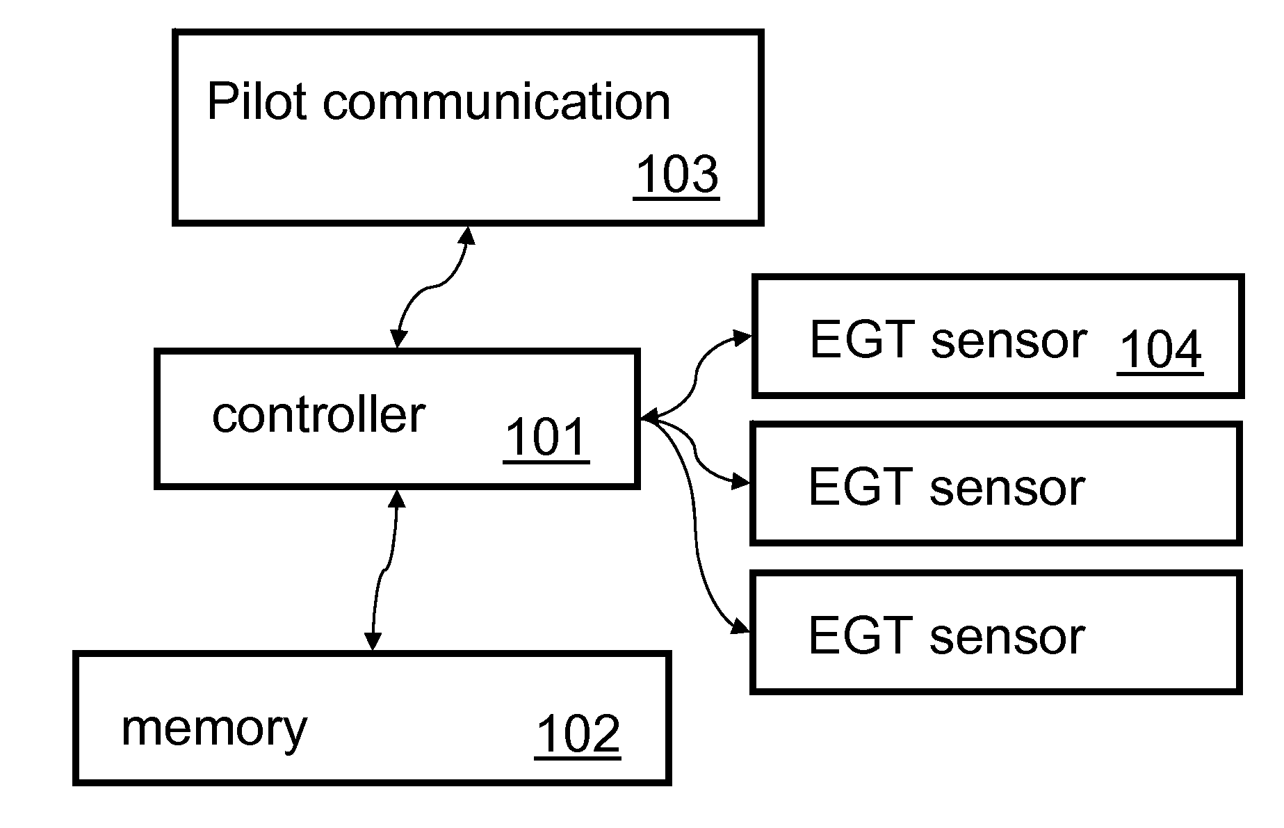
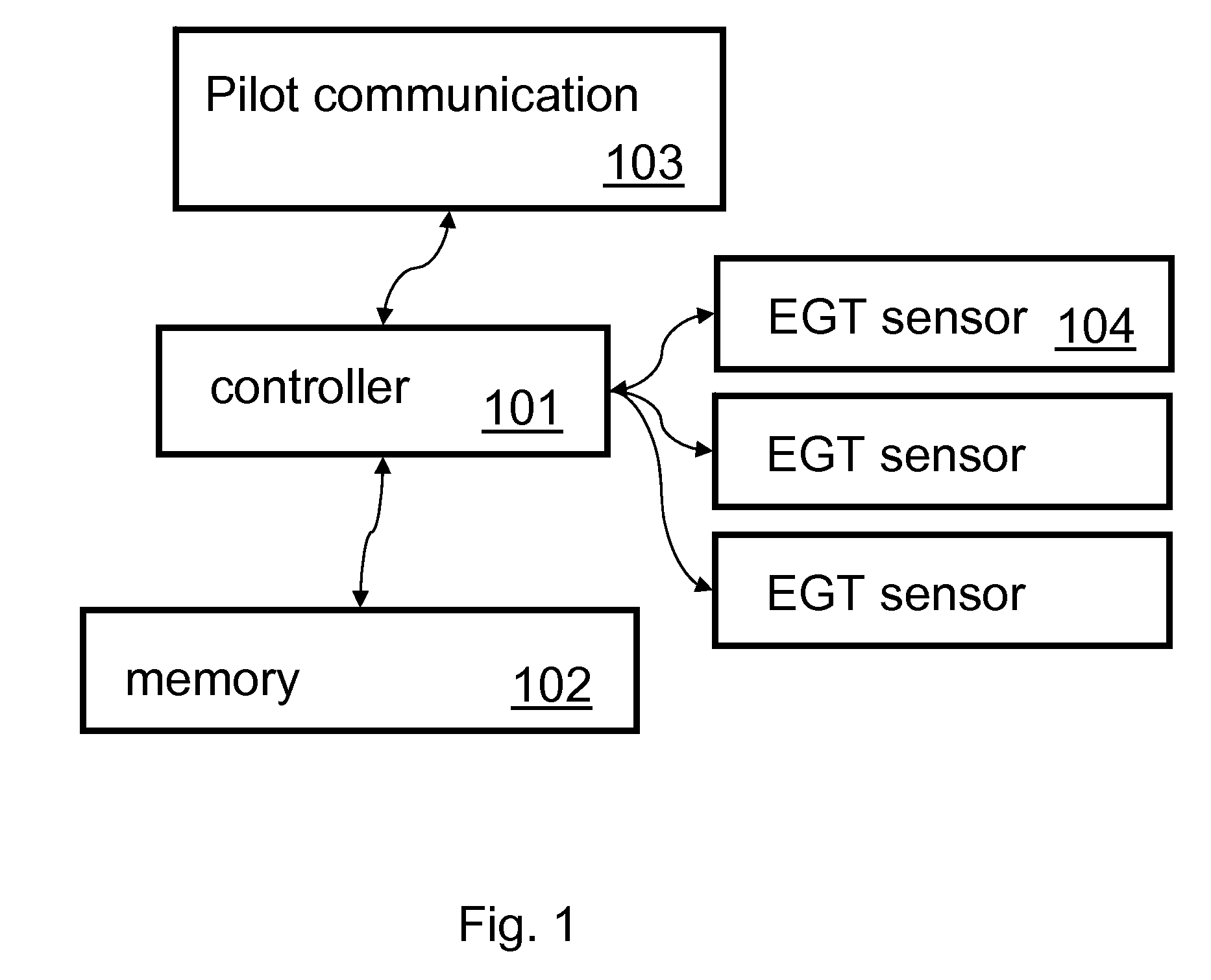
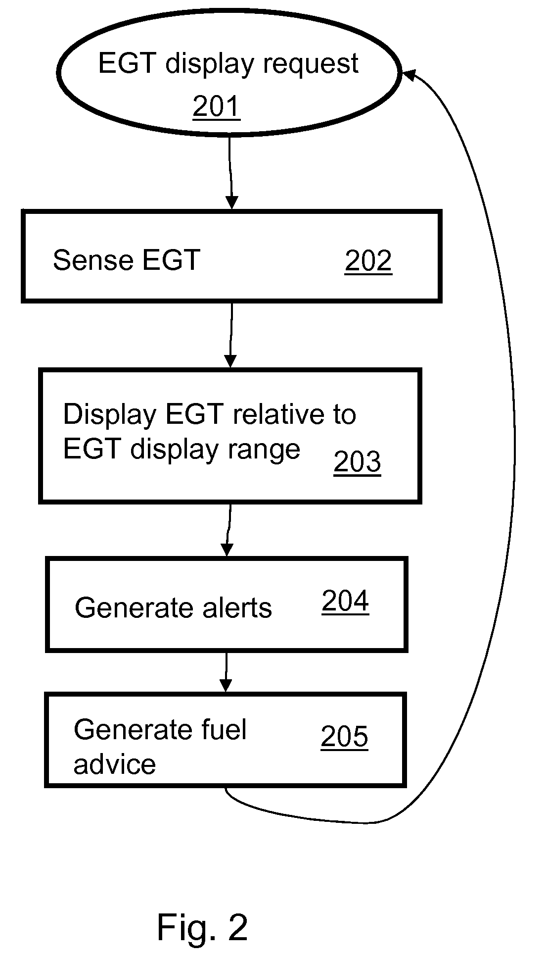
The present invention provides a computer-implemented function that monitors and displays exhaust gas temperatures in an engine. The function includes a lean climb function that allows for easy reading of exhaust gas temperatures on a specific cylinder and provides a means for leaning while in a climb. This efficient leaning reduces fuel consumption and the chance of harmful conditions that can lead to engine failure. The function also provides a display of exhaust gas temperatures in multiple cylinders, allowing the pilot to have a more comprehensive view of the engine's performance. The function can also display exhaust gas temperatures in response to pilot requests, allowing the pilot to only focus on the information that is relevant to the operation of the aircraft. The invention includes sensors mounted with the engine to sense the exhaust gas temperature of one or more cylinders and a controller to read the sensors and allow the pilot to input requests for an exhaust gas temperature display, desired display ranges, target exhaust gas temperatures, reference cylinder identification, temperatures at which to generate alerts, or combinations therof. The controller can use the display to communicate the exhaust gas temperature of the reference cylinders, as well as highlight temperatures that are near or exceed temperature ranges or limits and provide alerts to the pilot when temperatures are near or exceed limits.

Problems solved by technology

The large range displayed on the bar graphs makes it difficult to precisely manage the EGT temperature graphically.
The analog temperature display can allow for more precise reading of EGT, but does not allow setting (or adjusting) of temperature range reminders, target temperature, change in specification of a reference cylinder, or alerts if the sensed temperature goes out of an adjustable target range.

Method used


Image

  • Aircraft Exhaust Gas Temperature Monitor
  • Aircraft Exhaust Gas Temperature Monitor
  • Aircraft Exhaust Gas Temperature Monitor

Examples


example embodiment

[0031]FIG. 6 is a schematic block diagram of an example embodiment of the present invention. A Display Panel accommodates communication of information to a pilot. A Switch Panel accommodates communication of information from a pilot. A single or dual redundant controller(s) can be used to determine state, to set controls, to control the display, to accept input in between the sensors and the display / switch. Sensors corresponding to various attributes of aircraft, such as those discussed above, provide information to the controller. The controller determines the state of the aircraft from the attributes, for example as described above. The controller sends information to the display which accepts input based on the determined state. For example, the controller can accept input from one or more switches, where the switches are defined to have specific meanings depending on the determined state. The controller initiates control of various aircraft attributes, for example those describe...


PUM


Abstract

A computer-implemented function monitors and displays exhaust gas temperatures (EGT) in a plurality of cylinders in an engine. The invention provides an easy way to read exhaust gas temperature on a specific cylinder, and to provide a means for leaning the engine while in a climb. Efficient leaning in a climb reduces fuel consumption and reduces the chance of harmful conditions that can lead to engine failure.

Description

CROSS-REFERENCE TO RELATED APPLICATIONS[0001]This application claims the benefit of U.S. provisional application 60 / 853,712, filed Oct. 23, 2006, which is incorporated herein by reference. This application claims the benefit as a continuation-in-part of U.S. patent application Ser. No. 11 / 311,060, filed Dec. 19, 2005, which is incorporated herein by reference.[0002]This application is related to the following applications, each of which is incorporated herein by reference:[0003]Aircraft Emergency Handling, U.S. patent application Ser. No. ______, filed on the same date hereof;[0004]Backup Electrical Power System for Solid-State Aircraft Power Distribution Systems, U.S. patent application Ser. No. ______, filed on the same date hereof;[0005]Aircraft Electrical System Evaluation, U.S. patent application Ser. No. ______, filed on the same date hereof;[0006]Variable Speed Flap Retraction and Notification, U.S. patent application Ser. No. ______, filed on the same date hereof.FIELD OF TH...

Claims


Application Information

Patent Timeline
Patent Type & Authority Applications(United States)
IPC IPC(8): G06F7/00
CPCF05B2260/80F05B2270/1064Y02T50/677G01D7/00F05D2270/0831F05D2260/80G01D2207/10Y02T50/60
Inventor AUSMAN, MARCDEVRIES, KEVIN
Owner ASTRONICS ADVANCED ELECTRONICS SYST
Learn More