Method and Device for Processing Crankshaft and Burnishing Roller for Crankshaft

a technology of burnishing roller and crankshaft, which is applied in the direction of crankshafts, grinding machines, manufacturing tools, etc., can solve the problems of high manufacturing cost and complex structure of the burnishing apparatus disclosed in the patent document 1, and achieve the effect of improving the surface properties of the crankshaft shank which is free of fillets, improving the surface properties and simplifying the structure of the crankshaft machining apparatus

Inactive Publication Date: 2009-12-17
HONDA MOTOR CO LTD
View PDF0 Cites 18 Cited by
  • Summary
  • Abstract
  • Description
  • Claims
  • Application Information

AI Technical Summary

Benefits of technology

[0015]It is a general object of the present invention to provide an apparatus for machining a crankshaft to improve surface properties of a shank of the crankshaft which is free of fillets.
[0016]A major object of the present invention is to provide a method of machining a crankshaft to improve surface properties of a shank of the crankshaft which is free of fillets.
[0017]Another object of the present invention is to provide an apparatus for machining a crankshaft, the apparatus being simplified in structure and less costly to manufacture.
[0018]Still another object of the present invention is to provide a crankshaft burnishing roller for improving surface properties of a shank of a crankshaft which is free of fillets and for appropriately burnishing the shank even if an oil hole is defined therein.
[0020]According to the present invention, therefore, the shank has surface properties improved by a machining method which is simpler than heretofore. As a result, the surface properties of the shank of the crankshaft which is free of fillets are improved, and a crankshaft machining apparatus is simplified in structure and less costly to manufacture.
[0022]According to the present invention, therefore, the surface properties of the shank of the crankshaft which is free of fillets are improved, and even if the oil hole is present in the region to be burnished, the shank can appropriately be burnished.

Problems solved by technology

The burnishing apparatus disclosed in Patent Documents 1, 2 are complex in structure and highly costly to manufacture because they need a plurality of components including the pair of support rollers (support members), the backup roller, etc.

Method used


Image

  • Method and Device for Processing Crankshaft and Burnishing Roller for Crankshaft
  • Method and Device for Processing Crankshaft and Burnishing Roller for Crankshaft
  • Method and Device for Processing Crankshaft and Burnishing Roller for Crankshaft

Examples


Embodiment Construction

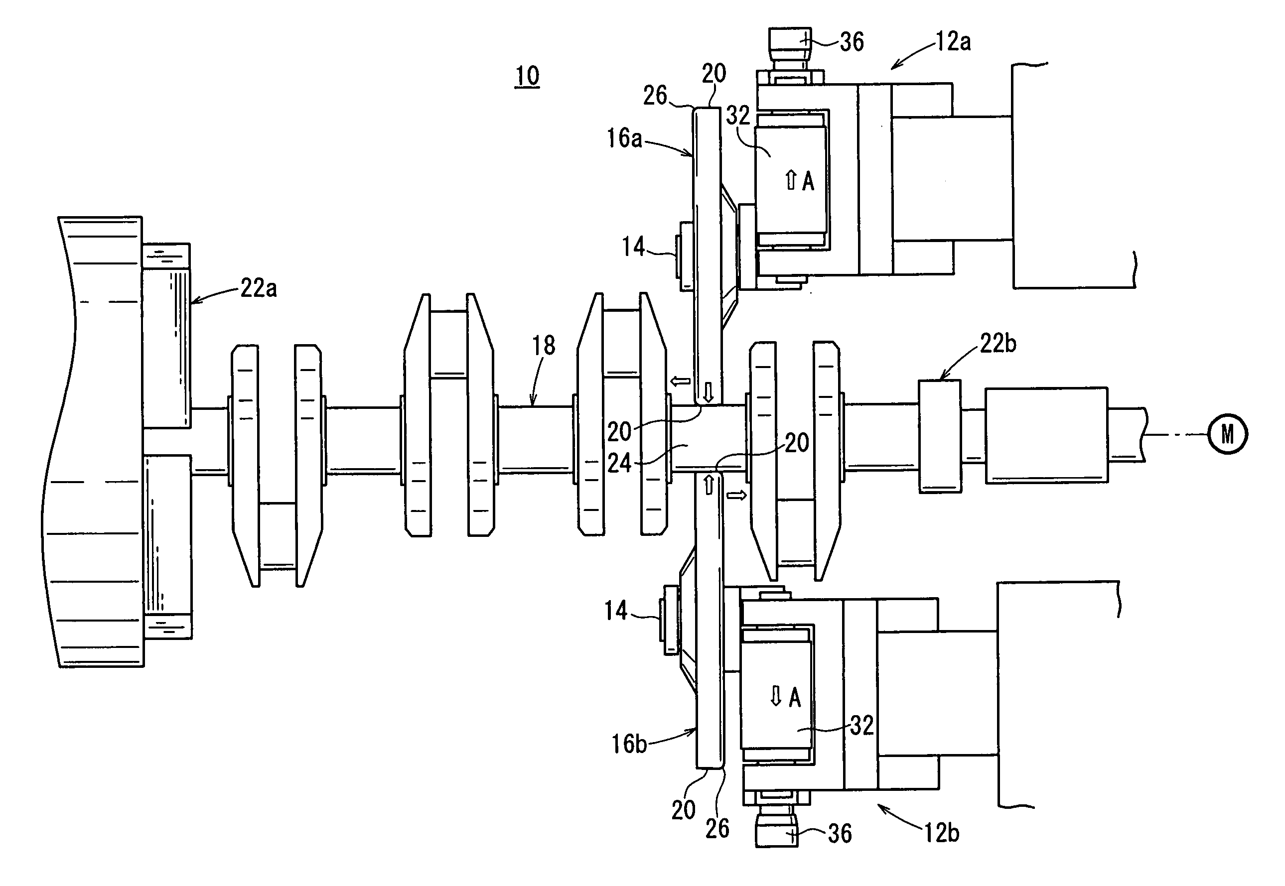
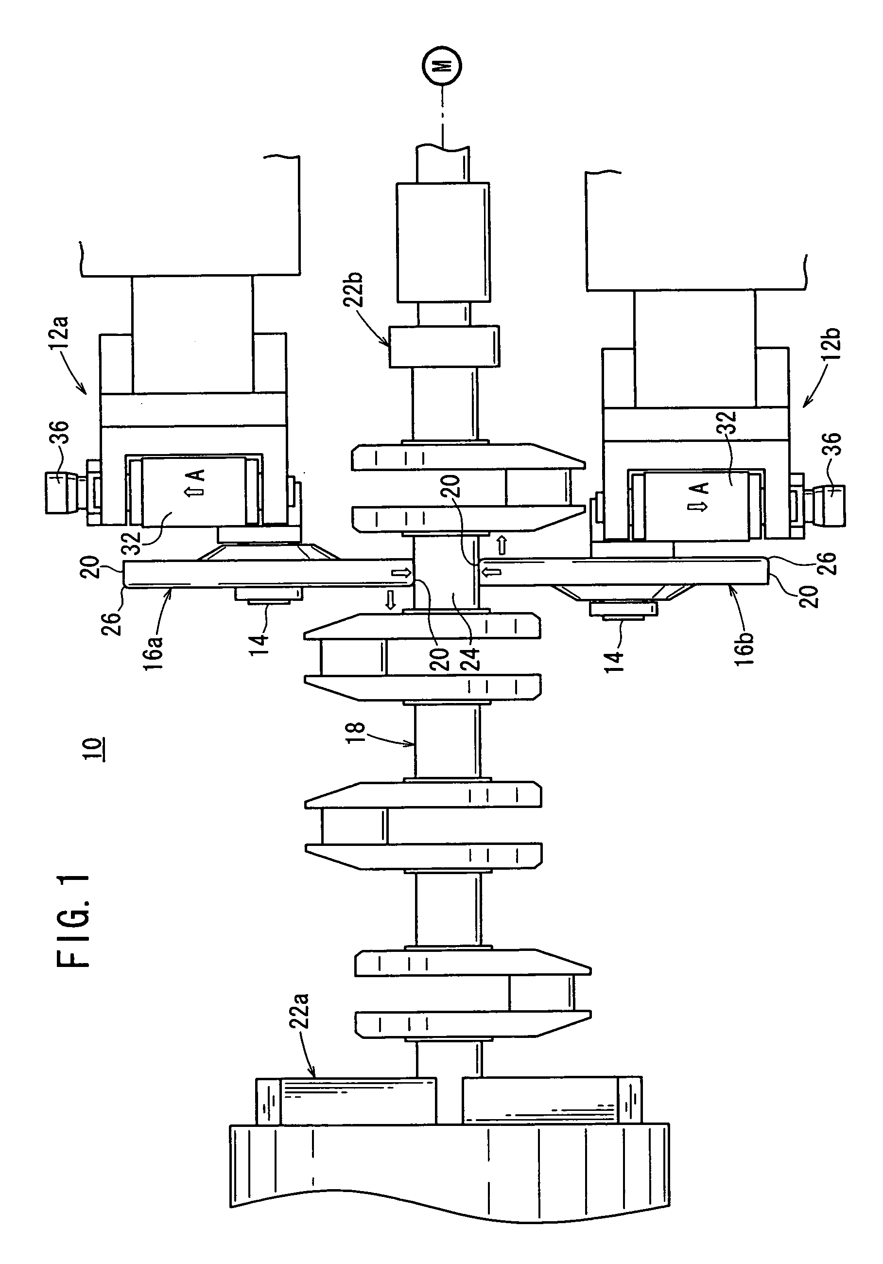
[0040]In FIG. 1, the reference character 10 represents a crankshaft machining apparatus according to an embodiment of the present invention.

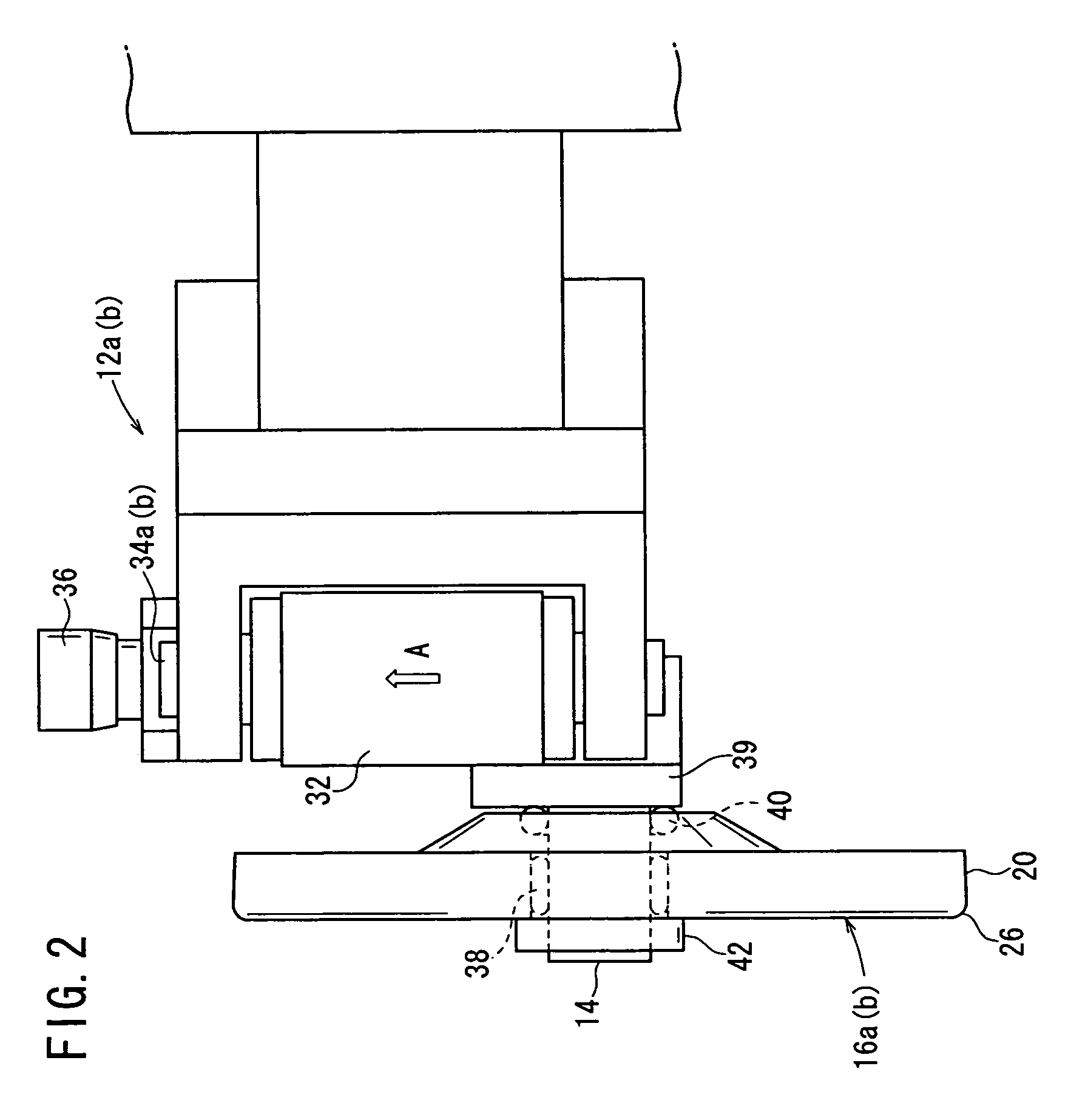
[0041]The crankshaft machining apparatus 10 is mounted on the turret (or rotary tool base) of a turret lathe (or a machining center) which is controlled by a numerical control system, not shown. The crankshaft machining apparatus 10 comprises first and second adapters 12a, 12b displaceable in the directions of three axes X, Y, Z which are perpendicular to each other, a pair of burnishing rollers 16a, 16b rotatably supported respectively on rotational shafts 14 of the first and second adapters 12a, 12b, and first and second holding mechanisms 22a, 22b for engaging respective both axial ends of a crankshaft 18 (hereinafter referred to as workpiece 18) and holding the workpiece 18 such that the workpiece 18 can be rotated about its own axis by a rotary drive source M.

[0042]The burnishing rollers 16a, 16b are disposed in mutually opposite relation t...


PUM

PropertyMeasurementUnit
angle θ1aaaaaaaaaa
angleaaaaaaaaaa
shapeaaaaaaaaaa

Abstract

A pair of burnishing rollers formed in a roughly disk shape are linearly disposed oppositely to each other on both sides of the shaft part of a crankshaft. The crankshaft is rotated about its axis by the rotatingly driving action of a rotating driving source (M). The pair of burnishing rollers are displaced in a direction apart from each other while the shaft part of the crankshaft is held by the outer peripheral surfaces of the pair of burnishing rollers to apply a rolling to the crankshaft.

Description

TECHNICAL FIELD[0001]The present invention relates to a method of and an apparatus for machining (processing) a crankshaft to burnish a shank of the crankshaft for vehicle engines or the like, and a crankshaft burnishing roller for burnishing a shank of a crankshaft by rollingly pressing an outer surface of the shank of the crankshaft.BACKGROUND ART[0002]Heretofore, it is known to burnish a shank of a crankshaft for engines for increased productivity and improved surface properties of the shank.[0003]For example, Patent Document 1 discloses a technical idea for making the machining surface pressure of the burnishing roller applied from a burnishing roller to a shank lower at both ends of the burnishing roller than at the center thereof in order to prevent both ends of the shank of the crankshaft from being rounded.[0004]Patent Document 1 discloses a roller burnishing apparatus for burnishing a crankshaft with a burnishing roller, the apparatus including a pair of support rollers by ...

Claims


Application Information

Patent Timeline
Patent Type & Authority Applications(United States)
IPC IPC(8): B24B39/04
CPCB24B5/42Y10T29/47F16C3/06B24B39/04
Inventor CHIBA, DAISUKEKAWASUMI, KATSUYUKIMORI, EITSUGU
Owner HONDA MOTOR CO LTD
Why Eureka
Try Eureka