Composite material, and light emitting element and light emitting device using the composite material
- Summary
- Abstract
- Description
- Claims
- Application Information
AI Technical Summary
Benefits of technology
Problems solved by technology
Method used
Image
Examples
embodiment 1
[0135]In this embodiment, a composite material of the present invention is explained. The composite material of the invention contains a carbazole derivative represented by the following general formula (1) and an inorganic compound.
[0136]In the formula, R11 and R13 may be either the same or different, each of which represents any one of hydrogen, an alkyl group having 1 to 6 carbon atoms, an aryl group having 6 to 25 carbon atoms, a heteroaryl group having 5 to 9 carbon atoms, an arylalkyl group, and an acyl group having 1 to 7 carbon atoms; Ar11 represents one of an aryl group having 6 to 25 carbon atoms and a heteroaryl group having 5 to 9 carbon atoms; R12 represents any one of hydrogen, an alkyl group having 1 to 6 carbon atoms, and an aryl group having 6 to 12 carbon atoms; R14 represents any one of hydrogen, an alkyl group having 1 to 6 carbon atoms, an aryl group having 6 to 12 carbon atoms, and a substituent represented by General Formula (2). In the substituent represented...
embodiment 2
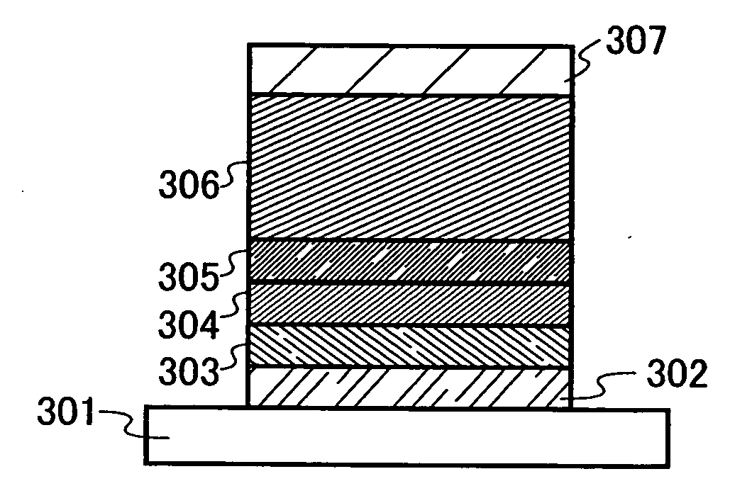
[0170]A light emitting element of the present invention has a plurality of layers between a pair of electrodes. The plurality of layers is a laminate of a combination of layers formed of a material having a high carrier injection property and a material having a high carrier transport property such that a light emitting region is formed apart from the electrodes, in other words, such that carriers are recombined in a portion distant from the electrodes.
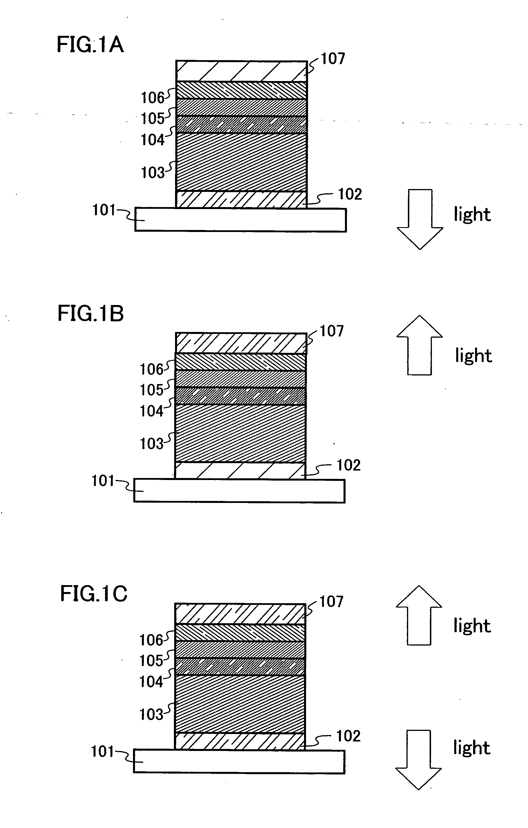
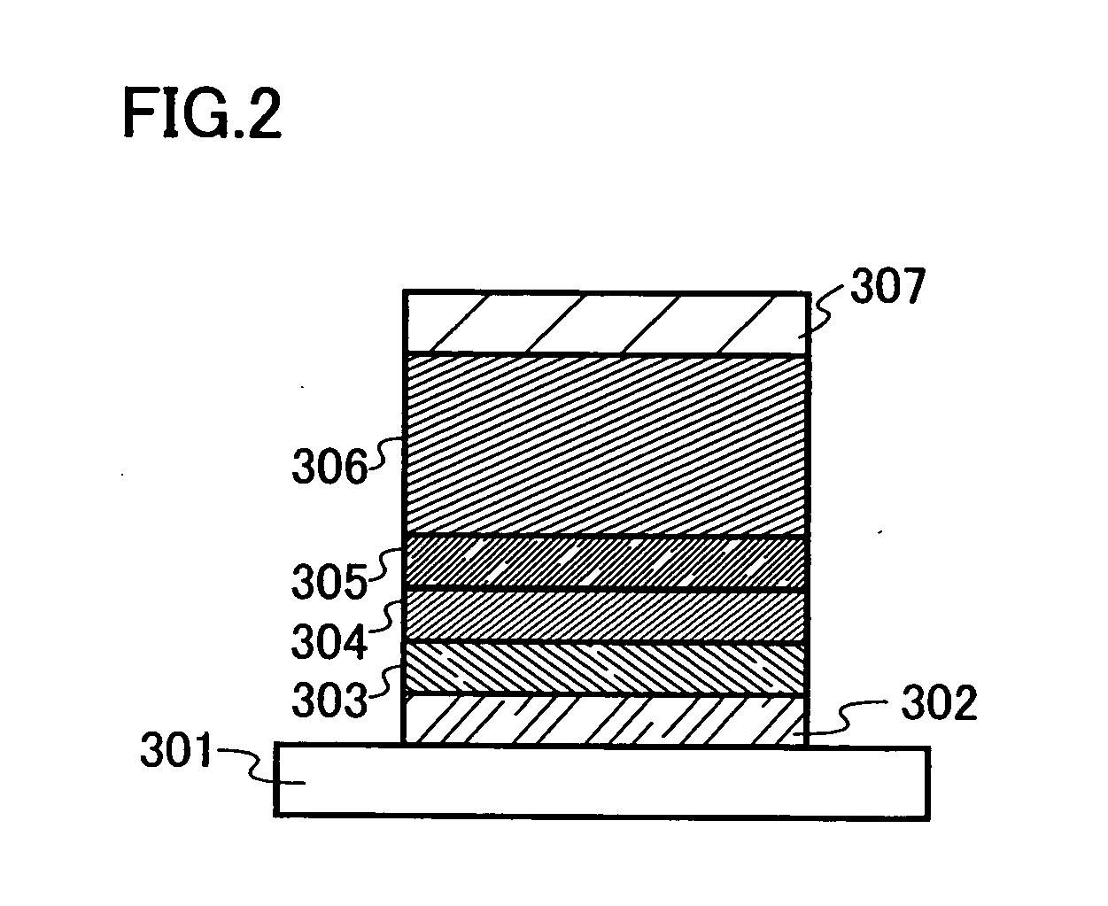
[0171]One mode of the light emitting element of the invention is hereinafter explained with reference to FIG. 1A.
[0172]In this embodiment, the light emitting element includes a first electrode 102, a first layer 103, a second layer 104, a third layer 105, and a fourth layer 106 which are sequentially laminated over the first electrode 102, and a second electrode 107 which is further provided thereover. Note that in this embodiment, explanation is made hereinafter assuming that the first electrode 102 functions as an anode and the seco...
embodiment 3
[0196]In this embodiment, a light emitting element having a structure different from that described in Embodiment 2 is explained with reference to FIGS. 5A to 5C and 6A to 6C. In a structure to be described in this embodiment, a layer containing the composite material of the invention can be provided to be in contact with an electrode serving as a cathode.
[0197]An example of a structure of a light emitting element of the invention is shown in FIG. 5A. In the structure, a first layer 411, a second layer 412, and a third layer 413 are laminated between a first electrode 401 and a second electrode 402. In this embodiment, the case where the first electrode 401 functions as an anode and the second electrode 402 functions as a cathode, is explained.
[0198]The first electrode 401 and the second electrode 402 can employ the same structure as that in Embodiment 2. The first layer 411 is a layer which contains a material having a high light emitting property. The second layer 412 is a layer w...
PUM
 Abstract
Description
Claims
Application Information
 - R&D
- Intellectual Property
- Life Sciences
- Materials
- Tech Scout
- Unparalleled Data Quality
- Higher Quality Content
- 60% Fewer Hallucinations
Browse by: Latest US Patents, China's latest patents, Technical Efficacy Thesaurus, Application Domain, Technology Topic, Popular Technical Reports.
© 2025 PatSnap. All rights reserved.Legal|Privacy policy|Modern Slavery Act Transparency Statement|Sitemap|About US| Contact US: help@patsnap.com


