Motor Structure
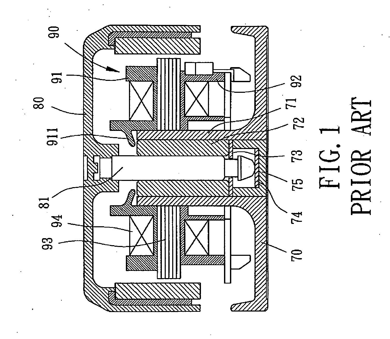
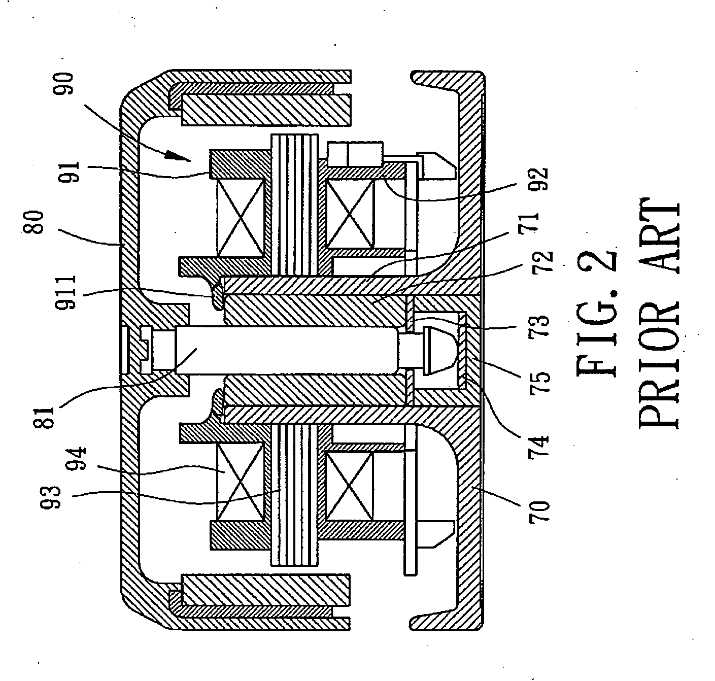
a technology of motor structure and shaft tube, which is applied in the direction of bearing unit rigid support, recording information storage, instruments, etc., can solve the problems of b>71/b> not providing a reliable positioning effect, easy noise, and abutting portion breakag
- Summary
- Abstract
- Description
- Claims
- Application Information
AI Technical Summary
Benefits of technology
Problems solved by technology
Method used
Image
Examples
first embodiment
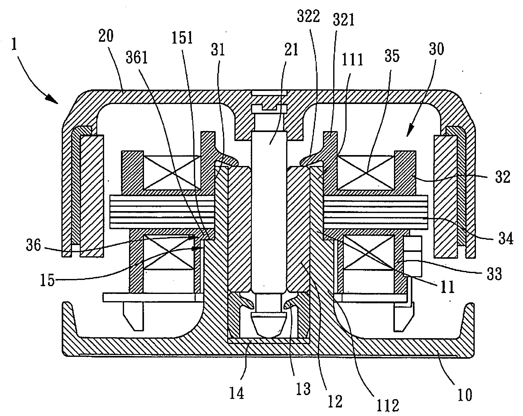
[0024]A motor structure of a first embodiment according to the preferred teachings of the present invention is shown in FIGS. 3 and 4 of the drawings and generally designated 1. According to the preferred form shown, motor structure 1 includes a housing 10, a rotor 20, and a stator 30. Housing 10 includes a hollow shaft tube 11 having a sealed bottom. Shaft tube 11 receives a bearing 12, a retaining plate 13, and a supporting plate 14. Shaft tube 11 includes a positioning section 15 on an outer periphery thereof. According to the most preferred form shown, shaft tube 11 includes an upper section 111 and a lower section 112 having an outer diameter larger than that of upper section 111, forming an annular shoulder 151 between the upper and lower sections 111 and 112. Annular shoulder 151 forms positioning section 15.
[0025]Rotor 20 includes a shaft 21 in a central portion thereof. Shaft 21 is rotatably extended through bearing 22. Thus, rotor 20 can rotate on top of housing 10.
[0026]S...
second embodiment
[0027]FIGS. 5 and 6 show a motor structure 3 of a second embodiment according to the preferred teachings of the present invention modified from motor structure 1, wherein positioning section 15 of shaft tube 11 includes a plurality of annularly spaced blocks 152 on the outer periphery thereof and spaced from a top edge of shaft tube 11, the engaging portion 36 of lower bobbin 33 includes an annular flange 362 on the inner periphery thereof. A bottom face of annular flange 362 rests on and is positioned by top faces of blocks 152. Namely, blocks 152 of shaft tube 11 provides annular flange 362 of lower bobbin 33 with an axial supporting force along the longitudinal axis of shaft tube 11. Thus, stator 30 is positioned in the fixed axial position relative to bearing 12 with abutting portion 322 abutting bearing 12 to prevent bearing 12 from disengaging from shaft tube 11.
third embodiment
[0028]FIGS. 7 and 8 show a motor structure 4 of a third embodiment according to the preferred teachings of the present invention modified from motor structure 3, wherein positioning section 15 of shaft tube 11 includes a plurality of annularly spaced semi-spherical protrusions 153 on the outer periphery thereof, and engaging portion 36 of lower bobbin 33 includes an annular groove 363 on an inner periphery thereof. Protrusions 153 are engaged in annular groove 363 to provide tight coupling between stator 30 and shaft tube 11. Protrusions 153 of shaft tube 11 provide lower bobbin 33 with an axial supporting force along the longitudinal axis of shaft tube 11. Thus, positioning stator 30 is positioned in the fixed axial position with abutting portion 322 abutting bearing 12 to prevent bearing 12 from disengaging from shaft tube 11.
PUM
 Abstract
Description
Claims
Application Information
 - R&D
- Intellectual Property
- Life Sciences
- Materials
- Tech Scout
- Unparalleled Data Quality
- Higher Quality Content
- 60% Fewer Hallucinations
Browse by: Latest US Patents, China's latest patents, Technical Efficacy Thesaurus, Application Domain, Technology Topic, Popular Technical Reports.
© 2025 PatSnap. All rights reserved.Legal|Privacy policy|Modern Slavery Act Transparency Statement|Sitemap|About US| Contact US: help@patsnap.com


