Apparatus for supplying stable, isolated DC power and method of making same

a technology of isolated dc power and amplifier, applied in the field of power supplies, can solve the problems of increasing the size and cost of dc power supplies for those amplifiers, increasing the cost of the system, and increasing the cost of components, so as to minimize the variance of each rectifier dc output voltage and minimize the variance of each dc output.

Active Publication Date: 2009-12-17
GENERAL ELECTRIC CO
View PDF13 Cites 25 Cited by
  • Summary
  • Abstract
  • Description
  • Claims
  • Application Information

AI Technical Summary

Benefits of technology

[0010]According to one aspect of the invention, a power supply having an input, wherein the power supply includes a multi-winding transformer having an input and a plurality of outputs, and a plurality of rectifiers to provide a plurality of DC output voltages, wherein each rectifier is coupled to an output of the multi-winding transformer. The power supply further includes a regulator circuit coupled between the transformer input and one of the transformer outputs, and configured to regulate an input voltage to the multi-winding transformer to minimize a variance of each rectifier DC output voltage.
[0011]In accordance with another aspect of the invention, an MRI apparatus includes a magnetic resonance imaging (MRI) system having a plurality of gradient coils positioned about

Problems solved by technology

Gradient amplifiers comprise a major portion of the total cost of an MR imaging system.
As the size of gradient amplifiers increase to provide improved imaging functionality, the size and cost of DC power supplies for those amplifiers also increase.
Also, for high-voltage operation, resonant converters use specialized components increasing the cost of the system.
Resonant converters, which operate at high frequencies, include switches and rectifier diodes capable of handling elevated power levels at high frequencies, making the components more difficult to manufacture, and therefore more expensive.
Similarly, the high-frequency transformers needed to operate resonant converters

Method used


Image

  • Apparatus for supplying stable, isolated DC power and method of making same
  • Apparatus for supplying stable, isolated DC power and method of making same
  • Apparatus for supplying stable, isolated DC power and method of making same

Examples


Embodiment Construction

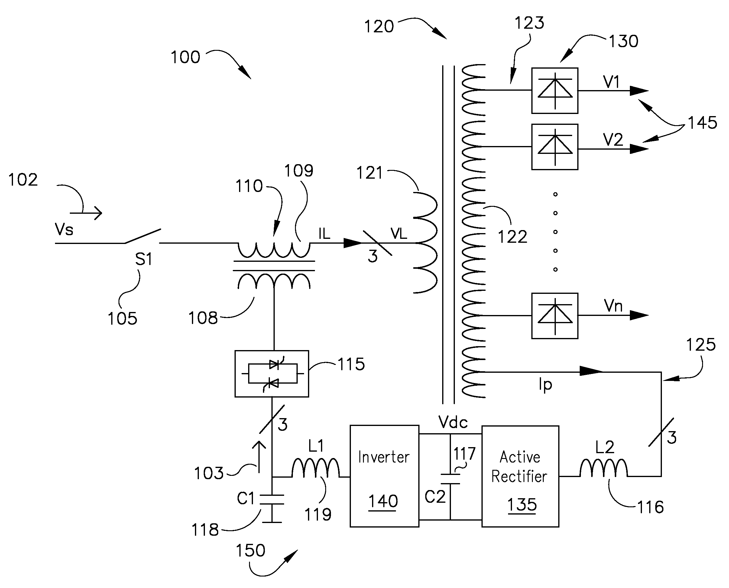
[0027]FIG. 1 illustrates a schematic diagram of an isolated power supply 100 according to one embodiment of the invention. Power supply 100 will be described herein as a three-phase power supply. Power supply 100 has a three-phase AC input 102 configured to be coupled to unregulated three-phase AC power. A switch 105 connects or disconnects the AC input 102, as necessary, to a transformer 110 coupled thereto. A winding, such as a secondary winding 109 of transformer 110, is also coupled to a primary winding 121 of a multi-winding transformer 120. As will be described herein below, transformer 110 provides isolation for a pre-regulator, or control, circuit 150 from the AC input 102.

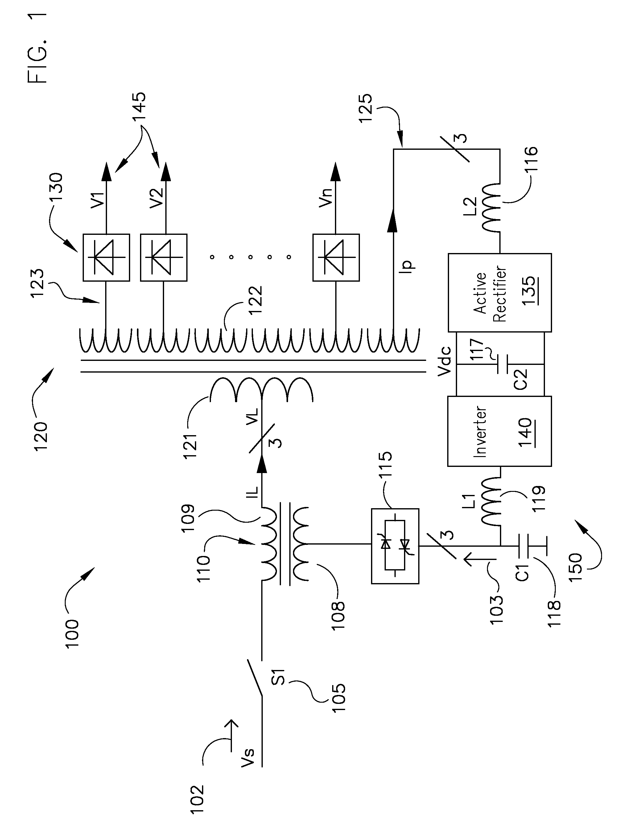
[0028]Multi-winding transformer 120 has a plurality of secondary windings 122, hence the term multi-winding transformer. The plurality of secondary windings 122 of multi-winding transformer 120 have a plurality of outputs 123 coupled to a plurality of unregulated rectifiers 130. FIG. 2 shows an exemplary s...


PUM


Abstract

A power supply having an input, wherein the power supply includes a multi-winding transformer having an input and a plurality of outputs, and a plurality of rectifiers to provide a plurality of DC output voltages, wherein each rectifier is coupled to an output of the multi-winding transformer. The power supply further includes a regulator circuit coupled between the transformer input and one of the transformer outputs, and configured to regulate an input voltage to the multi-winding transformer to minimize a variance of each rectifier DC output voltage.

Description

BACKGROUND OF THE INVENTION[0001]Embodiments of the invention relate generally to power supplies and, more particularly, to an apparatus for supplying multi-channel, isolated, and stable DC power. While embodiments of the invention may be described with respect to a magnetic resonant imaging system, one skilled in the art will recognize that the invention may be used in any device where multiple channels of isolated, stable DC power is desired.[0002]When a substance such as human tissue is subjected to a uniform magnetic field (polarizing field B0), the individual magnetic moments of the spins in the tissue attempt to align with this polarizing field, but precess about it in random order at their characteristic Larmor frequency. If the substance, or tissue, is subjected to a magnetic field (excitation field B1) which is in the x-y plane and which is near the Larmor frequency, the net aligned moment, or “longitudinal magnetization”, MZ, may be rotated, or “tipped”, into the x-y plane...

Claims


Application Information

Patent Timeline
IPC IPC(8): G01V3/02H02J1/04
CPCH02M7/217H02M2001/0093H02M2001/009H02M1/0093H02M1/009
Inventor ZHU, PENGCHENGSABATE, JUAN ANTONIOLIU, YUNFENG
Owner GENERAL ELECTRIC CO
Why Eureka
Try Eureka