System and method for testing light-emitting devices

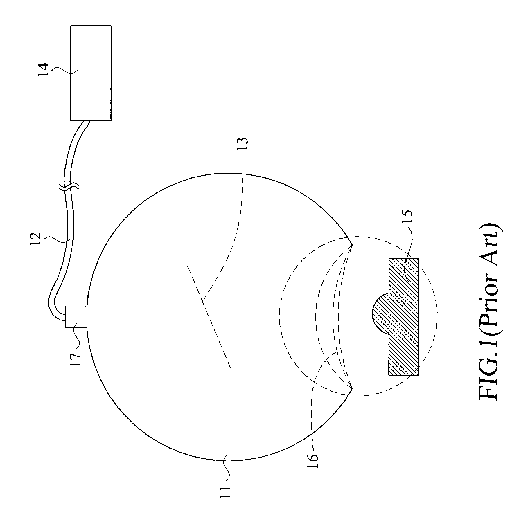
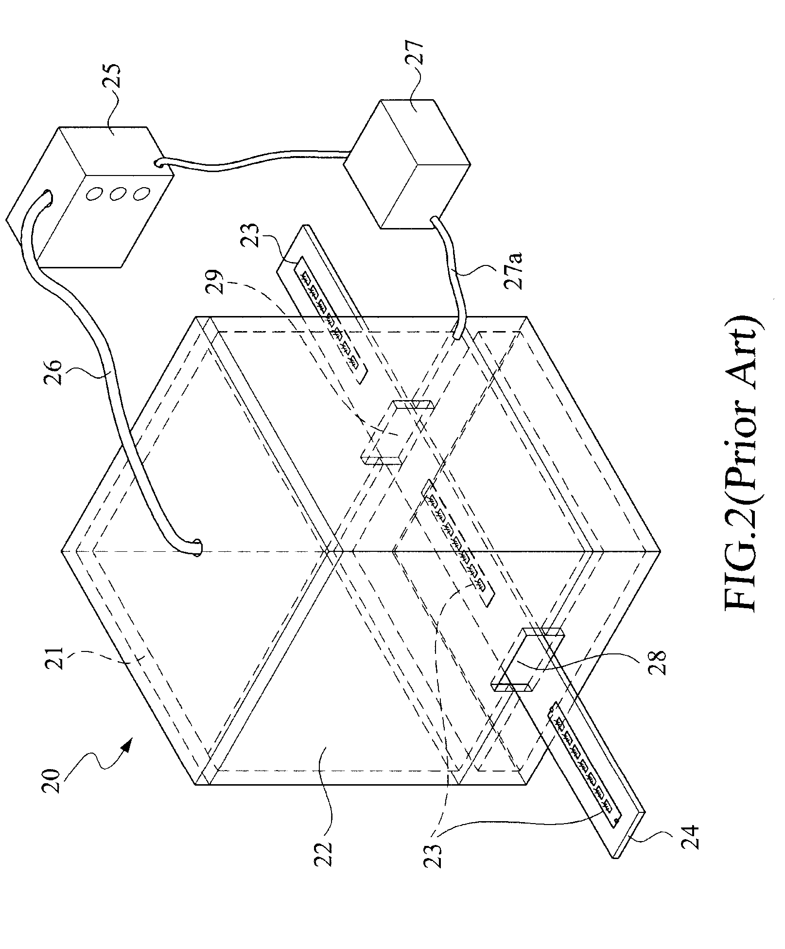
a technology of light-emitting devices and systems, which is applied in the direction of individual semiconductor device testing, optical radiation measurement, instruments, etc., can solve the problems of limited use of integrating spheres, inevitable labor load and time-consumption, and the cost of integrating spheres b>11/b> is often not affordable to all those they need, so as to achieve quick and precise positioning

Active Publication Date: 2009-12-17
CHROMA ATE
View PDF6 Cites 21 Cited by
  • Summary
  • Abstract
  • Description
  • Claims
  • Application Information

AI Technical Summary

Benefits of technology

[0011]Accordingly, it is an object of the present invention is to provide a system for testing light-emitting device

Problems solved by technology

Further, the size of the integrating sphere 11 and the accompanying facilities usually limits the usage of the integrating sphere 11 only in the laboratory.
In addition, reciprocally positioning and replacing the light-emitting devices (LED 15 for example) for testing outside the input port 16 can some

Method used


Image

  • System and method for testing light-emitting devices
  • System and method for testing light-emitting devices
  • System and method for testing light-emitting devices

Examples


Embodiment Construction

[0038]The invention disclosed herein is directed to a system and a method for testing light-emitting devices. In the following description, numerous details are set forth in order to provide a thorough understanding of the present invention It will be appreciated by one skilled in the art that variations of these specific details are possible while still achieving the results of the present invention. In other instance, well-known components are not described in detail in order not to unnecessarily obscure the present invention.

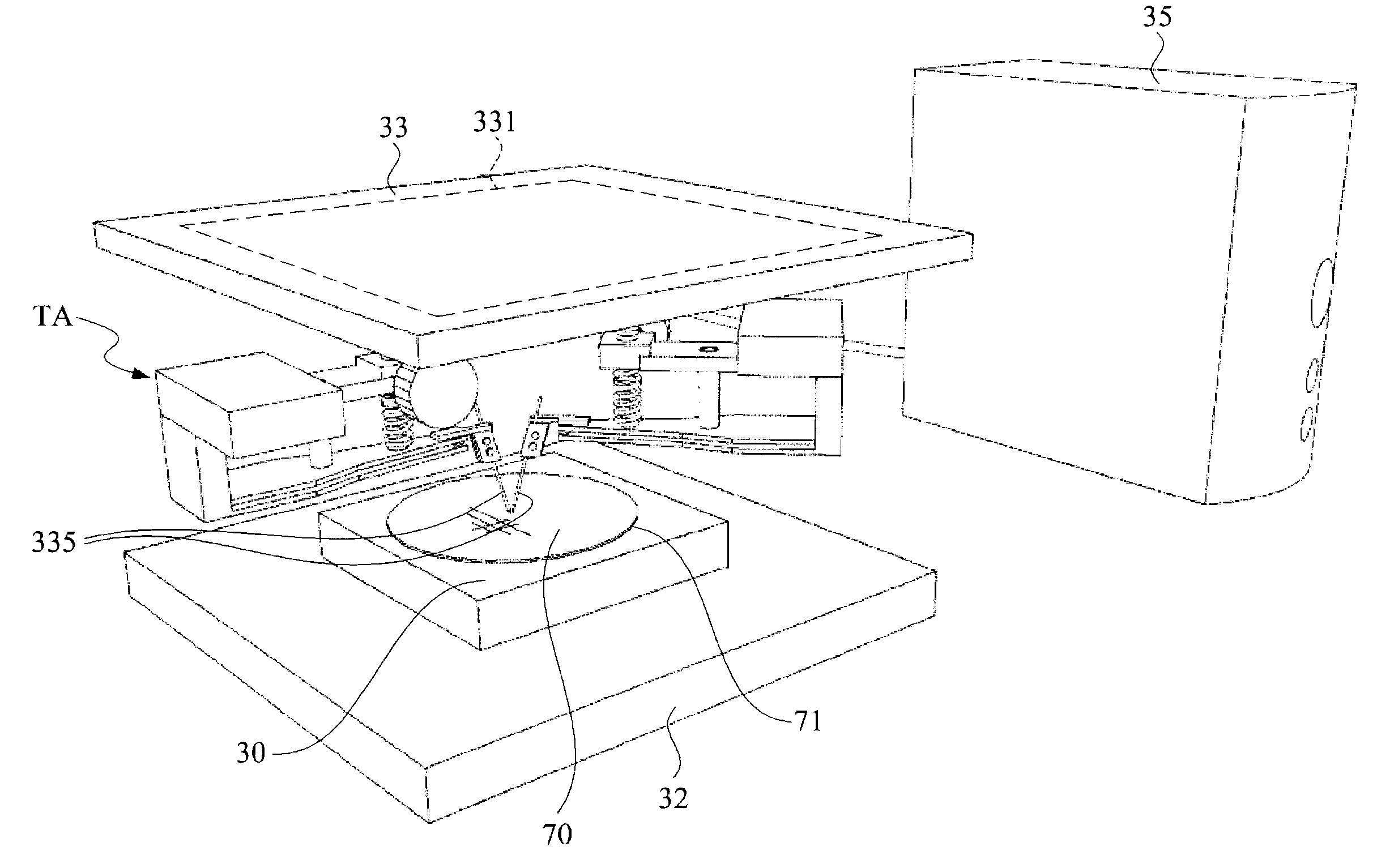
[0039]In the following description, the light-emitting device is realized in a light-bar form having a plurality of light-emitting elements arranged thereon in a longitudinal direction. Also, some structures or linkages to form the machinery of the present invention may be omitted so as not to obscure the description and drawings.

[0040]Referring now to FIG. 4, a block diagram of the test system in accordance with the present invention is shown. The system inc...


PUM


Abstract

A method for testing light-emitting devices in a batch-wise, associated with a system for the same purpose, comprises the steps of: preparing the light-emitting devices on a moving carrier unit in a manner of aligning a predetermined longitudinal direction of the light-emitting devices with a predetermined transportation direction of the moving carrier unit, each of the light-emitting devices further having plural light-emitting elements; transporting orderly the light-emitting devices to pass a test area on a base of the system, in which the base energizes only the light-emitting elements within the test area; and, a solar cell module detecting continuously the energized light-emitting elements within the test area and further forming signals with respect to photo energy received in the test area.

Description

[0001]This application claims the benefit of two Taiwan Patent Applications, Serial No. 097210477 filed Jun. 13, 2008 and Serial No. 097136723 filed Sept. 24, 2008, and the subject matter of which is incorporated herein by referenceBACKGROUND OF THE INVENTION[0002](1) Field of the Invention[0003]The invention relates to a system and an accompanying method for testing light-emitting devices, and more particularly to the test station / equipment and the test method that utilize solar cells / cell modules.[0004](2) Description of the Prior Art[0005]In the art, to obtain the total luminous flux (or say, lumen) of a light-emitting device, an integrating sphere is usually used. The operation of a typical integrating sphere can be concisely elucidated in FIG. 1. As shown, an integrating sphere 11 is connected with an optical spectrum analyzer 14 via an optical fiber 12. The integrating sphere 11 further includes thereinside a diffusing baffle 13. An LED to be tested 15 is positioned at an inpu...

Claims


Application Information

Patent Timeline
IPC IPC(8): G01R31/00G01R31/01
CPCG01J1/02G01J1/0223G01J1/4228G01R31/2635G01J2001/4247G01R31/01G01J2001/0481
Inventor TSENG, I-SHIHLEE, JEFFCHANG, MIN-HUNG
Owner CHROMA ATE
Why Eureka
Try Eureka