Information processing system, information processing apparatus, information processing method, and program

a technology of information processing and information processing apparatus, applied in the field of information processing technique of processing moving image data, can solve the problems of image disorder, complex addition of ts to video signal, and inability to obtain pts in the same way as in the audio signal, so as to eliminate image disorder

Inactive Publication Date: 2009-12-17
CANON KK
View PDF9 Cites 23 Cited by
  • Summary
  • Abstract
  • Description
  • Claims
  • Application Information

AI Technical Summary

Benefits of technology

[0045]The present invention has been made in consideration of the above-described problems. The present invention provides an information processing technology which can eliminate disorder in an image by suppressing any data arrival after a timestamp by predicting a time required for image processing such as video quality enhancement processing and predicting a data arrival time at a video output unit.

Problems solved by technology

It is therefore impossible to obtain the PTS in the same way as in the audio signal.
As described above, TS addition to a video signal is more complex than for an audio signal.
For this reason, the packet receiving-side apparatus may be unable to output video data at the time represented by the timestamp, resulting in disorder in the image.
On the other hand, if the timestamp is set too late, the capacity of packets to be held by the packet receiving-side apparatus may increase, resulting in buffer overflow.
However, this method does not necessarily allow display at a time designated by a timestamp.
It is therefore impossible to prevent underflow or overflow only by simple transmission interval adjustment.

Method used


Image

  • Information processing system, information processing apparatus, information processing method, and program
  • Information processing system, information processing apparatus, information processing method, and program
  • Information processing system, information processing apparatus, information processing method, and program

Examples


first embodiment

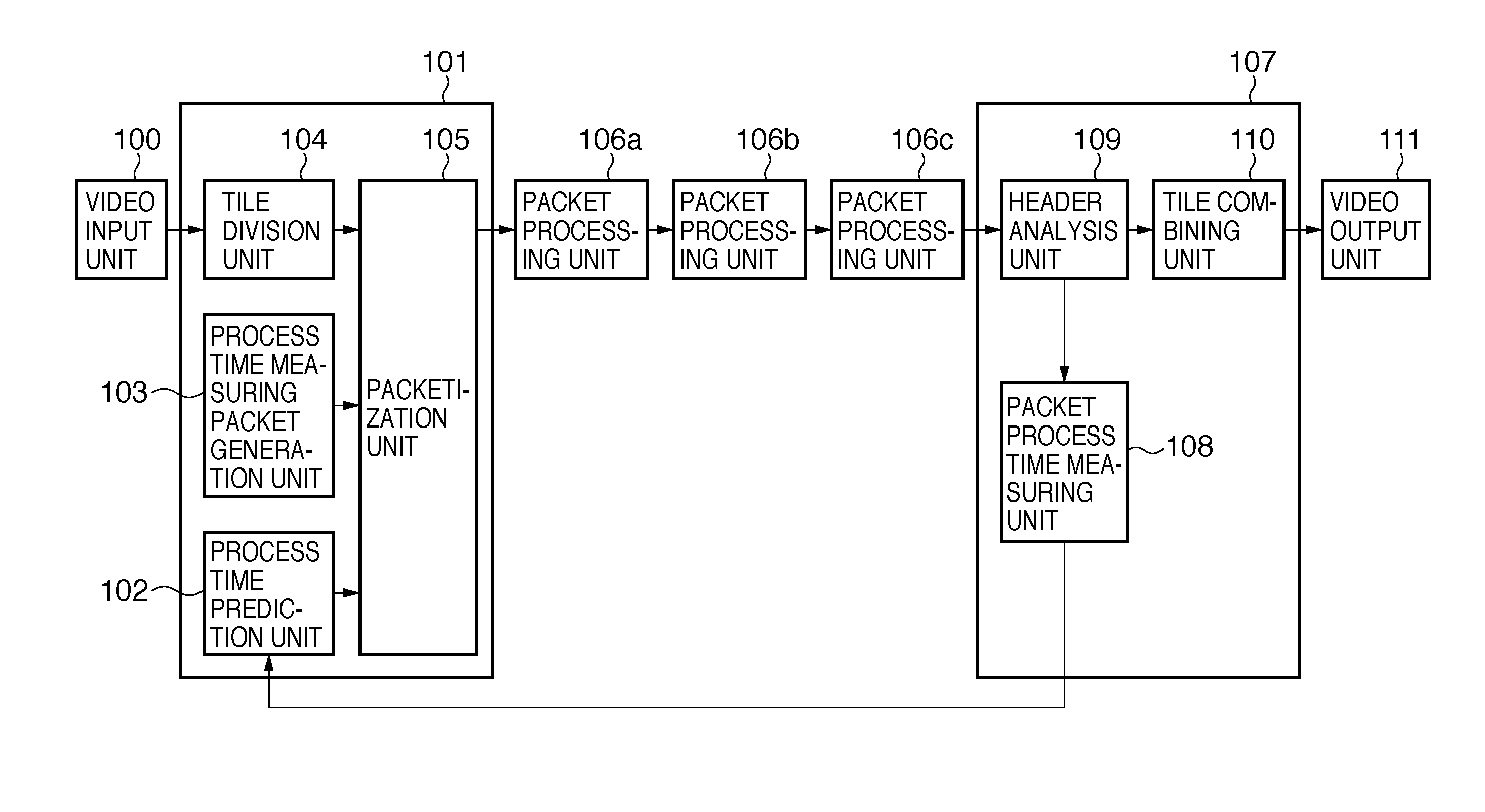
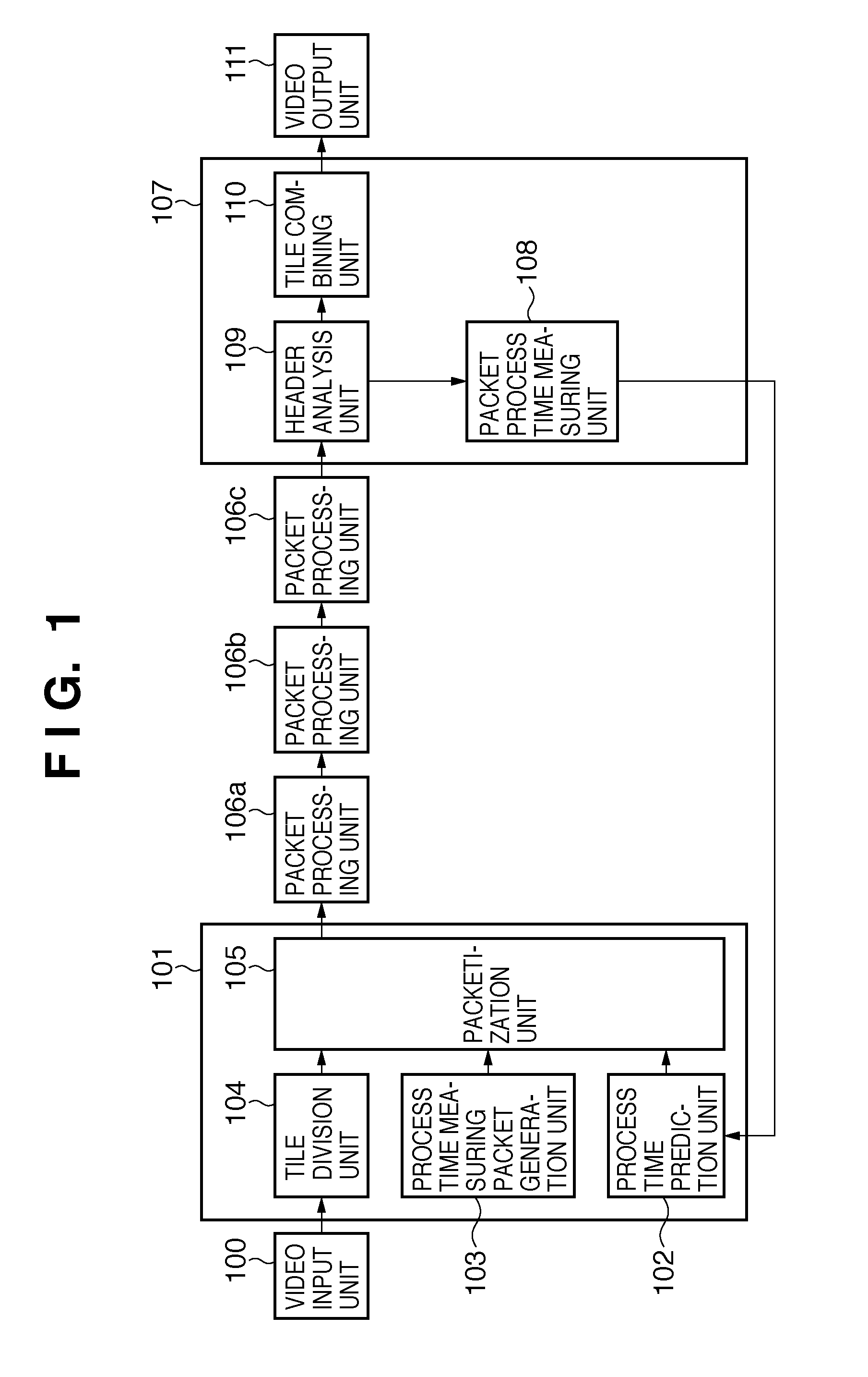
[0087]FIG. 1 is a block diagram showing the arrangement of an information processing system (to also be referred to as a “moving image processing system” hereinafter) according to the first embodiment of the present invention. The moving image processing system can divide a moving image into tiles, and packetize and process information corresponding to each divided tile. A video input unit 100 is connected to a tile division unit 104 in a packet generation unit 101. The packet generation unit 101 receives video data from the video input unit 100 and generates packets. The packet generation unit 101 includes the tile division unit 104, a process time measuring packet generation unit 103, a process time prediction unit 102, and a packetization unit 105.

[0088]The tile division unit 104 is connected to the packetization unit 105. The tile division unit 104 receives video data from the video input unit 100 and divides it into tiles. This embodiment will be explained assuming that video d...

second embodiment

[0111]FIG. 3 is a block diagram showing the arrangement of a moving image processing system according to the second embodiment of the present invention. Referring to FIG. 3, a video input unit 300 is connected to a tile division unit 304 and a video data analysis unit 303 in a packet generation unit 301. The packet generation unit 301 receives an input from the video input unit 300 and generates packets. The packet generation unit 301 includes the tile division unit 304, the video data analysis unit 303, a process time prediction unit 302, and a packetization unit 305. The tile division unit 304 is connected to the packetization unit 305, and is the same as the tile division unit 104 described in the first embodiment.

[0112]The video data analysis unit 303 is connected to the video input unit 300 and the process time prediction unit 302. The video data analysis unit 303 analyzes an input moving image (video data) and extracts feature information of the moving image (the resolution, m...

third embodiment

[0122]The arrangement of an information processing apparatus 800 according to the third embodiment will be described with reference to FIGS. 8 and 9. FIG. 8 is a block diagram showing an example of the functional arrangement of the information processing apparatus 800 according to this embodiment.

[0123]The information processing apparatus 800 includes a reception unit 801, processing unit 802, transmission unit 803, process stop judging unit 804, measuring unit 805, and permissible process time holding unit 806. All or some of the elements can be implemented by hardware such as circuits or software.

[0124]The reception unit 801 receives a packet obtained by dividing video data from another apparatus. The other apparatus can be either another information processing apparatus 800 or a video transmission apparatus 1010 to be described later. The reception unit 801 outputs the received packet to the processing unit 802 and simultaneously notifies the measuring unit 805 of the packet rece...


PUM


Abstract

An information processing system for performing processing of dividing a moving image into tiles and packetizing and outputting information corresponding to each tile includes a process time measuring packet generation unit adapted to generate and transmit a process time measuring packet in which a packet sending time is set to measure a packet process time, a packet process time measuring unit adapted to measure, based on the packet sending time set in the process time measuring packet and the reception time of the process time measuring packet, the packet process time necessary for processing a packet, a determination unit adapted to determine, based on the packet process time, the timestamp of the moving image divided into the tiles, and a packetization unit adapted to execute processing of packetizing and outputting the timestamp and the information of the moving image divided into the tiles.

Description

BACKGROUND OF THE INVENTION[0001]1. Field of the Invention[0002]The present invention relates to an information processing technique and, more particularly, to an information processing technique of processing moving image data.[0003]2. Description of the Related Art[0004]A moving image compression / decompression transmission system for multiplexing and transmitting an audio signal and a video signal generally needs to cause its audio (sound) and video (image) signal processing units to output signals in synchronism.[0005]To enable synchronization between an image and sound, MPEG2 and MPEG1, which are international standard coding methods, use output timing information (information of the output time of a moving image) called a timestamp (to be referred to as a “TS” hereinafter). The TSs include a presentation timestamp (to be referred to as a “PTS” hereinafter) and a decoding timestamp (to be referred to as a “DTS” hereinafter).[0006]An MPEG system reproduces and outputs an audio si...

Claims


Application Information

Patent Timeline
Patent Type & Authority Applications(United States)
IPC IPC(8): H04N7/12
CPCH04N7/24H04N19/176H04N19/70H04N19/188H04N19/187H04N19/44H04N19/196
Inventor ODAGAWA, MASAYUKIOCHIAI, WATARUTAKAMURA, AKIHIRO
Owner CANON KK
Why Eureka
Try Eureka