T00l for rotary cutting machining

Active Publication Date: 2009-12-17
SECO TOOLS AB
View PDF11 Cites 39 Cited by
  • Summary
  • Abstract
  • Description
  • Claims
  • Application Information

AI Technical Summary

Benefits of technology

[0012]According to a favorable embodiment of the invention the stop surface of the respective coupling leg extends in parallel with the center axis of the tool body and the corresponding stop surface of the cutting head extends in parallel with the center axis of the cutting head. By letting the stop surfaces of the tool body be parallel with the center axis of the tool body, an achievement of these stop surfaces by mechanical machining of a blank prepared for the formation of a tool body is facilitated, and by letting the stop surfaces of the cutting head be parallel with the center axis of the cutting head, an achievement of these stop surfaces by mechanical machining of a blank prepared for the formation of a cutting head is facilitated.
[0013]According to another favorable embodiment of the invention, the angle between the stop surface of a coupling leg and the shoulder protruding from this stop surface is between 80-90°, preferably 90°. An angle of 90° is here particularly favorable, since this will give a right-angled design which facilitates the manufacturing of the tool body.
[0014]According to another favorable embodiment of the invention, there is in the normal state of the tool a clearance between the respective shoulder of the coupling legs and the corresponding shoulder of the cutting head when the cutting head is attached to the tool body. Hereby, there is no risk of wear between the mutually co-operating shoulders and the tolerance requirements on these shoulders will also be very low.
[0015]According to another favorable embodiment of the invention, each one of said shoulders of the cutting head is arranged on the upper side of the cutting head and preferably formed by a depression in a clearance surface arranged on the

Problems solved by technology

A disadvantage with these conical gripping surfaces is that the tolerance requirements are high for these surfaces and that they are relatively complicated to achieve by, means of mechanical machining.
The axial freedom of movement of the cutting head in relation to the tool body in th

Method used


Image

  • T00l for rotary cutting machining
  • T00l for rotary cutting machining
  • T00l for rotary cutting machining

Examples


Embodiment Construction

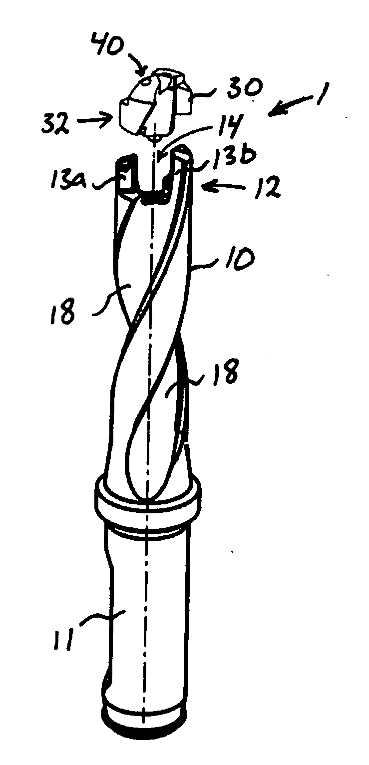
[0034]The tool 1 of the invention is intended to be rotated for cutting machining of a workpiece. In the illustrated example, the tool is designed as a twist drill, but the tool of the invention could also be designed as another type of tool for rotary cutting machining, such as for instance a milling cutter or the similar.

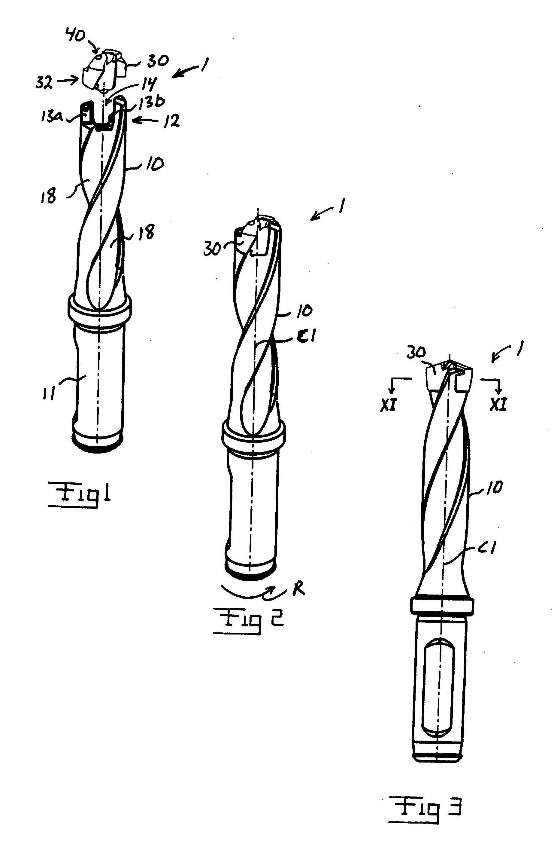
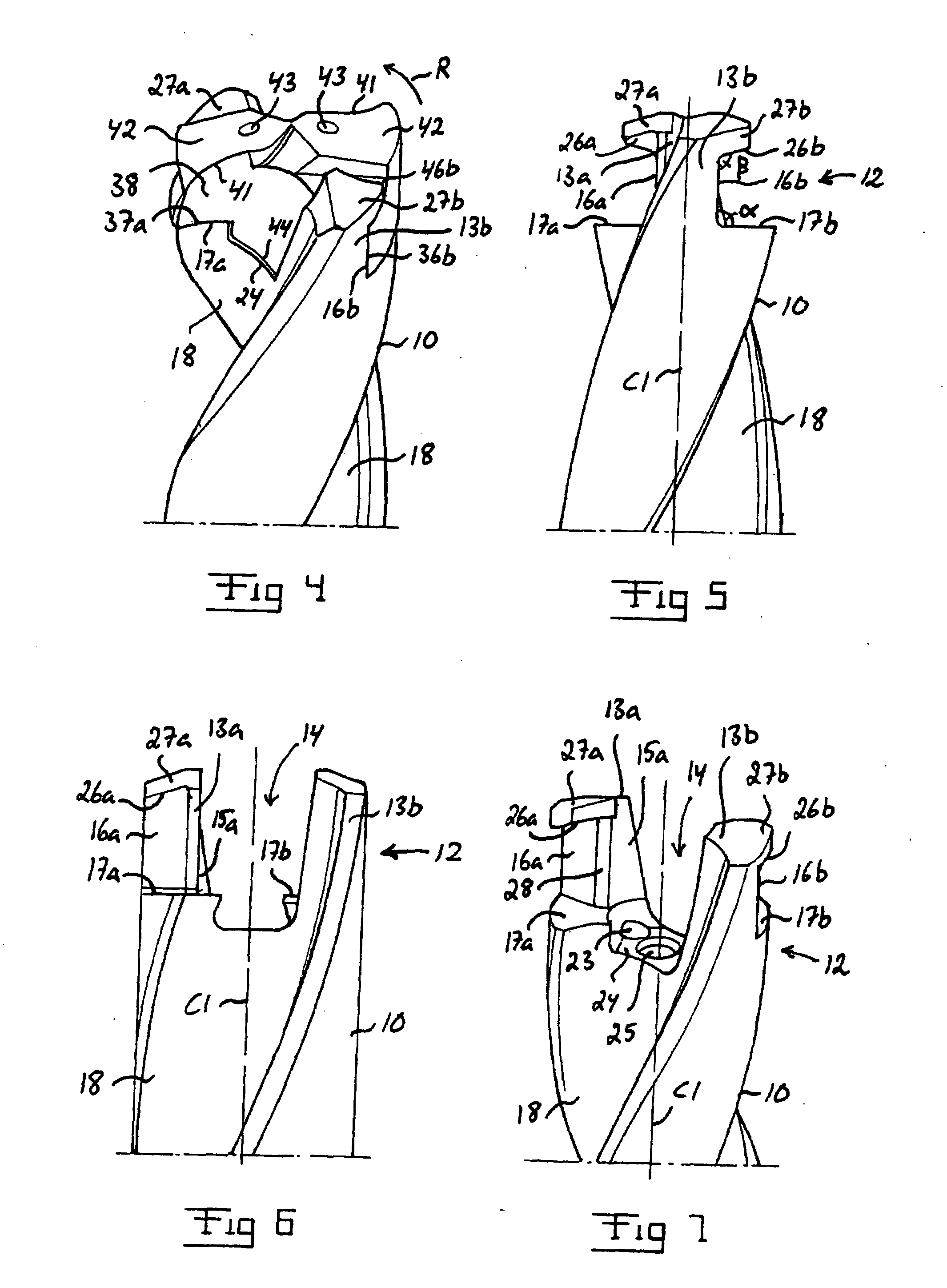
[0035]The intended direction of rotation of the tool 1 for machining is marked with the arrow R in FIGS. 2, 4 and 11-12. This direction of rotation is in the following denominated “machining direction of rotation” and consequently constitutes the direction in which the tool is intended to be rotated in order to achieve cutting machining of a, preferably metallic, workpiece. Alternatively, the workpiece can be rotated while the tool is kept stationary.

[0036]The tool 1 comprises a tool body 10 and a replaceable cutting head 30, which is detachably attachable to the tool body.

[0037]The cutting head 30 is formed in a one piece of a suitable cemented carbide, i.e. made...


PUM

PropertyMeasurementUnit
Angleaaaaaaaaaa
Angleaaaaaaaaaa
Angleaaaaaaaaaa

Abstract

A tool for rotary cutting machining includes a tool body and a replaceable cutting head detachably attachable to the tool body. At its front end, the tool body is provide with two coupling legs projecting in an axial direction. The respective coupling leg is provided with a stop surface for transferring torque from the tool body to the cutting head, which stop surface is designed for abutment against a corresponding stop surface of the cutting head. The respective coupling leg is provided with a shoulder protruding from the stop surface of the coupling leg. The cutting head is provided with two shoulders facing the front end of the cutting head and arranged on opposite sides of the center axis of the cutting head, which shoulders border on a respective one of said stop surfaces of the cutting head and are arranged to extend in under a respective one of said shoulders of the coupling legs of the tool body when the cutting head is attached to the tool body, so as to thereby present the cutting head from being displaced in axial direction away from the tool body. The invention also relates to a tool body and a cutting head included in such a tool.

Description

BACKGROUND AND SUMMARY[0001]The present invention relates to a tool for rotary cutting machining with a tool body and a replaceable cutting head detachably attachable to the tool body. The invention also relates to a tool body and a cutting head included in such a tool.[0002]A tool for rotary cutting machining is previously known from U.S. Pat. No. 5,988,953A and U.S. Pat. No. 5,971,673A. In this known tool, the mutual gripping surfaces of the tool body and the cutting head are conical and widen in the direction towards the rear end of the tool body and the cutting head, respectively, so as to thereby achieve a positive locking in axial direction between the tool body and the cutting head. This positive locking prevents the cutting head from being displaced in axial direction away from the tool body, for instance when the tool is pulled out of a bore drilled by means of the tool. A disadvantage with these conical gripping surfaces is that the tolerance requirements are high for thes...

Claims


Application Information

Patent Timeline
IPC IPC(8): B23B51/02
CPCB23B51/02B23B2205/02B23B2251/02B23B2251/50Y10T408/9097Y10T408/892Y10T408/907Y10T408/9098B23B2260/12B23B51/0003B23C5/22
Inventor FREJD, STEFAN
Owner SECO TOOLS AB
Why Eureka
Try Eureka